
Vertical shaft wind-driven generation system structure and control method thereof

A technology of a wind power generation system and a control method, which is applied to the control of wind turbines, wind energy power generation, wind turbines, etc., can solve the problems of poor self-starting capability of a lift-type system, low output efficiency of a drag-type system, and inability of the system to self-start, etc. Achieve the effect of reducing generator speed and output efficiency, improving self-starting capability and reducing output efficiency

Inactive Publication Date: 2012-03-28
TAIYUAN UNIVERSITY OF SCIENCE AND TECHNOLOGY
View PDF6 Cites 4 Cited by
  • Summary
  • Abstract
  • Description
  • Claims
  • Application Information

AI Technical Summary

Problems solved by technology

The vertical axis wind power generation system (hereinafter referred to as "the system") includes two types of lift type and resistance type. The advantages of the system are low noise, low vibration, and good integration with high-rise buildings. The problem is that the output of the resistance type system is Low efficiency and poor self-starting capability of lift-type systems
The vertical axis wind power generation systems with the above two structures have the disadvantages that the system cannot be self-started and the output power is low

Method used


Image

  • Vertical shaft wind-driven generation system structure and control method thereof
  • Vertical shaft wind-driven generation system structure and control method thereof
  • Vertical shaft wind-driven generation system structure and control method thereof

Examples


Embodiment Construction

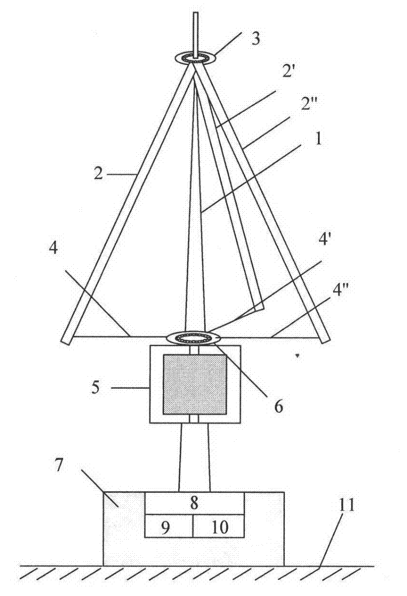
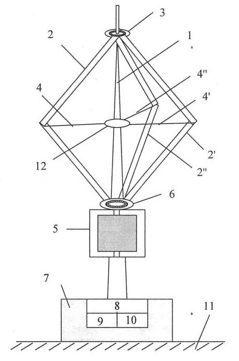
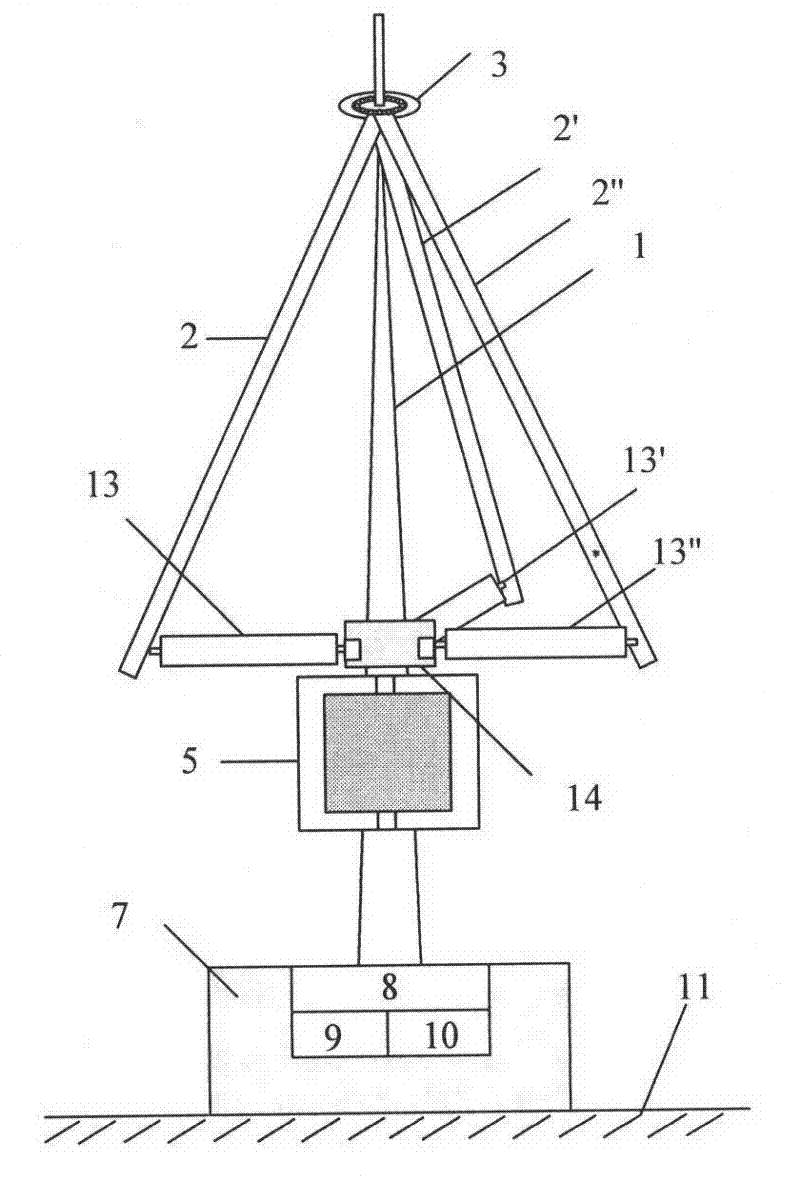
[0025] Taking the selected Δlift wind power generation system as an example, the rated power of the generator is 500W, the rated voltage is 50V, the rated current is 10A, the blade length of the fixed-pitch fan is 1.5m, and the blade length of the variable-pitch fan is 1.5m. The length is 0.8m, the width is 0.5m, the set cut-in wind speed is 3m / s, the cut-out wind speed is 20m / s, and the rated wind speed is 15m / s.

[0026]Taking the actual wind speed of 5m / s as an example, the steps of the control method are as follows: ①Set the rated power of the generator to 500W, the rated voltage to 50V, and the rated current to 10A. If the rated wind speed is 20m / s and the rated wind speed is 15m / s, perform step ②; ②The blades of the variable-pitch fan are perpendicular to the ground and close the braking device, and perform step ③; If there is technology, the output voltage value of the generator is 40V, the output current is 0.625A, and the output power is 25W, and the step ④ is execute...


PUM


Abstract

The invention discloses a vertical shaft wind-driven generation system structure and a control method thereof, belonging to the technical field of wind-driven generation. The structure comprises a bracket, a fixed pitch angle blade, a top combination component, a generator and a bottom combination component, wherein the top combination component consists of a bearing and top chassis; the bottom combination component comprises a braking device, a data gathering and controlling module, an energy consumption resistor and a base; the structure is characterized in that a fixed connecting rod in prior art is replaced by a middle control combination with adjustable and controllable pitch angle. The control method of the structure comprises the steps of: (1) setting an allowable value; (2) making the blade of a pitch variable fan vertical to the ground; (3) sampling an output signal regularly; (4) making a comparison between the collected value and the set value; (5) determining whether the collecting value is beyond the set value, if so, carrying out step (6), if not so, carrying out step (7); (6) making the blade of the pitch variable fan parallel to the ground; (7) changing the windward angle, and performing (8); (8) determining whether the wind speed is more than the rated wind speed, if so, access an energy consumption resistor, and returning to step (3); if not so, carrying out step (9); and (9) determining whether current wind speed is less than the accessed wind speed, if so, stopping operating the system, if not so, returning to step (3).

Description

technical field [0001] The invention belongs to the technical field of wind power generation, and in particular relates to a system structure and a control method of a vertical axis wind turbine with high self-starting performance and output efficiency under various wind speed conditions. technical background [0002] At present, the development and utilization of renewable energy has been increasingly concerned by the governments of various countries, and the domestic and foreign markets for converting wind energy into electrical energy through wind turbines are huge. According to the forecast of the EU Joint Research Center in 2004, by the end of this century, the proportion of wind power in the world's energy supply will exceed 10%. The vertical axis wind power generation system (hereinafter referred to as "the system") includes two types of lift type and resistance type. The advantages of the system are low noise, low vibration, and good integration with high-rise buildi...

Claims


Application Information

Patent Timeline
IPC IPC(8): F03D9/00F03D7/06
CPCY02E10/725Y02E10/72Y02E10/74
Inventor 刘立群刘春霞孔屹刚孙志毅
Owner TAIYUAN UNIVERSITY OF SCIENCE AND TECHNOLOGY
Learn More