
Calibration apparatus of on-site wide-range vacuum gauge and method thereof

A calibration method and wide-range technology, applied in the field of measurement, can solve the problems of large system, huge device, and expensive magnetic levitation rotor gauge, and achieve the effect of small size, wide range and high precision

Inactive Publication Date: 2012-03-28
江苏东方航天校准检测有限公司
View PDF5 Cites 14 Cited by
  • Summary
  • Abstract
  • Description
  • Claims
  • Application Information

AI Technical Summary

Problems solved by technology

[0002] The literature "Development of the Vacuum Measurement Standard Device by the Comparison Method", "Aerospace Measurement Technology" No. 66, No. 6, 1992, pages 70-73", introduced the calibration method and calibration system of the vacuum gauge by the comparison method, But its calibration range is 10 5 ~10 -4 Pa, and at 10 -1 ~10 -4 In the Pa pressure range, the magnetic levitation rotor gauge is used for measurement. The lower limit of this measurement method is limited by the lower limit of the magnetic levitation rotor gauge. At the same time, the cost of the magnetic levitation rotor gauge is relatively expensive. In addition, the system is relatively large, which is only suitable for use in the laboratory and cannot meet the requirements. Calibration requirements for on-site wide-range high-precision vacuum gauges
The document "Ultra-high standard vacuum device with dynamic flow method", "Journal of Vacuum Science and Technology", Volume 19, Issue 5, 1999, pages 400-402", introduces the method of calibrating vacuum gauges with constant pressure flowmeters, However, the development cost of the constant pressure flowmeter is high, and the device is very large. It is only suitable for laboratory calibration of ultra-high vacuum gauges, and cannot realize the calibration of wide-range vacuum gauges on site.

Method used


Image

  • Calibration apparatus of on-site wide-range vacuum gauge and method thereof
  • Calibration apparatus of on-site wide-range vacuum gauge and method thereof

Examples


Embodiment

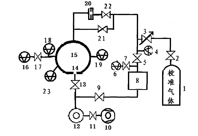
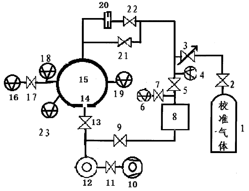
[0029] A wide range on-site vacuum gauge calibration device, including a gas source 1, a pressure reducing valve 2, a fine-tuning valve 3, a monitoring vacuum gauge 4, a first vacuum cut-off valve 5, a first capacitance film gauge 6, a second vacuum cut-off valve 7, Pneumatic chamber 8, first cut-off valve 9, mechanical pump 10, second solenoid valve 11, molecular pump 12, all-metal angle valve 13, vacuum chamber 15, second capacitive film gauge 16, third vacuum cut-off valve 17, first Three-capacitance film gauge 18, calibrated vacuum gauge 19, fourth vacuum shut-off valve 21 and fifth vacuum shut-off valve 22; limited-flow exhaust air hole 14 in the vacuum chamber 15; air inlet small hole in the fifth vacuum shut-off valve 22 20;

[0030] The connection relationship is as follows: one end of the decompression valve 2 is connected to the gas source 1 through a pipeline, the other end of the decompression valve 2 is connected to one end of the trim valve 3 through a pipeline, ...


PUM


Abstract

The invention, which belongs to the measurement technology field, relates to a calibration apparatus of an on-site wide-range vacuum gauge and a method thereof. The calibration apparatus comprises: an air source, a pressure-reducing valve, a micro-adjustable valve, a monitoring vacuum meter, five vacuum stop valves, three capacitance film gauges, a pressure stabilizing chamber, a first stop valve, a mechanical pump, a second solenoid valve, a molecular pump, an all-metal angle valve, a vacuum chamber, a calibrated vacuum gauge, and a vacuum monitoring vacuum gauge. Besides, a current limitingair exhaust micropore is arranged in the vacuum chamber; and an air inlet micropore is arranged in the fifth vacuum stop valve. In addition, according to the method, a calibration range of the vacuumgauge is in a pressure intensity rang of from 10 <5> to 10 <-7> Pa; a standard uncertainty within the pressure intensity range of from 10 <5> to 10 < -1> Pa is 1.5%; a standard uncertainty within therange of from 10 <-2> to 10 <-6> Pa is 2.0%; and when the pressure intensity is 10 <-7> Pa, a standard uncertainty is 5 %; and the method has advantages of wide measuring range and high precision andis suitable for on-site operation. Moreover, the apparatus has advantages of small volume and light weight.

Description

technical field [0001] The invention relates to a wide-range on-site vacuum gauge calibration device and method, belonging to the technical field of measurement. Background technique [0002] The literature "Development of the Vacuum Measurement Standard Device by the Comparison Method", "Aerospace Measurement Technology" No. 66, No. 6, 1992, pages 70-73", introduced the calibration method and calibration system of the vacuum gauge by the comparison method, But its calibration range is 10 5 ~10 -4 Pa, and at 10 -1 ~10 -4 In the Pa pressure range, the magnetic levitation rotor gauge is used for measurement. The lower limit of this measurement method is limited by the lower limit of the magnetic levitation rotor gauge. At the same time, the cost of the magnetic levitation rotor gauge is relatively expensive. In addition, the system is relatively large, which is only suitable for use in the laboratory and cannot meet the requirements. Calibration requirements for on-site wi...

Claims


Application Information

Patent Timeline
IPC IPC(8): G01L27/00
Inventor 卢耀文
Owner 江苏东方航天校准检测有限公司
Learn More