Fluid pump

A fluid pump and liquid pump technology, applied in the medical field, can solve the problems of high cost, unfavorable memory characteristics and normal functioning

Active Publication Date: 2012-03-28
ECP ENTWICKLUNGSGMBH
View PDF5 Cites 4 Cited by
  • Summary
  • Abstract
  • Description
  • Claims
  • Application Information

AI Technical Summary

Problems solved by technology

[0006] When using this material, in addition to the high cost of the starting material, one has to consider a whole host of additional mechanical issues, specifically related to memory properties and potentially detrimental to proper functioning

Method used


Image

  • Fluid pump
  • Fluid pump
  • Fluid pump

Examples


Embodiment Construction

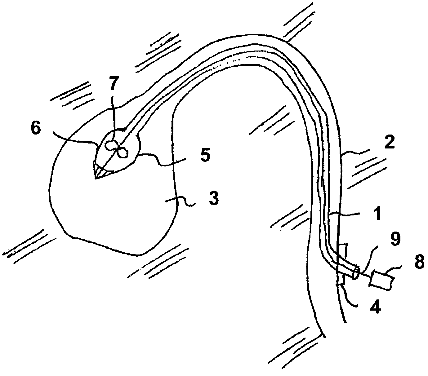
[0053] figure 1 It is shown that the catheter 1 is fed into the human blood vessel 2 directly to the ventricle 3, and passes through the blood vessel 4 through the lock 4. A catheter with a micropump 5 is guided through the lock into the ventricle 3 . To this end, when inserted, the pump is set in a retracted state, at which time the diameter of the pump casing 6 and the rotating element 7 is reduced in size. The design of this rotating element and pump housing does not present excessive restoring forces, which tend to resist the forces of the vessel wall to deploy the pump.

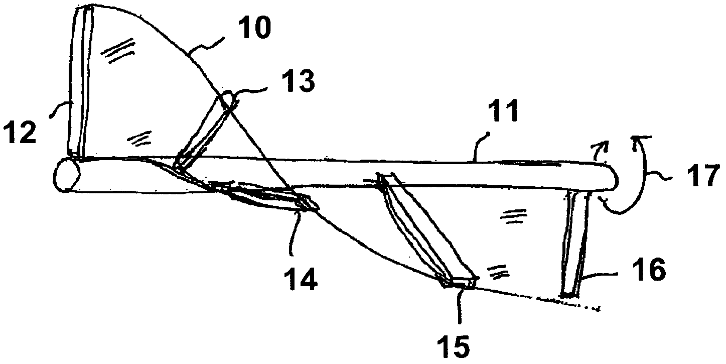
[0054] When the pump 5 has just been fed into the ventricle 3, the rotating element 7 can be rotated by means of the shaft 9 introduced through the catheter 1 in order to deliver the liquid. At the same time, if figure 2 It is shown that at least one rotating element vane is unfolded and erected by means of mechanical excitation or its own rotation, and by the action of the liquid back pressure when...


PUM


Abstract

The invention relates to a fluid pump, in particular liquid pump, with a rotor, with a rotor shaft (11) and with at least one rotor blade for delivering the fluid, wherein the rotor with regard to its diameter may be changed between a first, compressed condition, and a second expanded condition, wherein the at least one rotor blade comprises at least two erection elements (12, 13, 14) which are distanced to one another along the longitudinal axis (18) of the rotor shaft (11) and which project away from the shaft in the expanded condition of the rotor, as well as at least two limp rib elements (25, 26, 27, 28, 29, 30) which run at a distance to one another from one erection element (12, 13, 14) at least up to a further erection element, wherein a limp membrane (10) is held between the rib elements, which is tautened in the expanded condition of the rotor. A good compressibility of the rotor with low counter-forces, as well as a simple setting-up of the rotor may be achieved by the membrane-like design of the rotor blades. The membrane may for example be manufactured with the immersion method.

Description

technical field [0001] The invention relates to the field of medical technology, in particular to precision engineering technology, wherein the precision forming and manufacturing of technical components with small structural dimensions are at the forefront. Background technique [0002] This problem plays an important role, for example, in the construction of micropumps, which on the one hand require high performance and reliability, but on the other hand combine the smallest construction dimensions with ideal conveying performance with the lowest possible the cost of. [0003] Furthermore, in many medical applications, as well as other specialized applications, it is required that such pumps be able to be temporarily downsized in order to be delivered into hard-to-reach spaces, and then be able to be increased in size again after being delivered into the application space. Furthermore, in the medical field, it is also required that after the pump is used, for example, in ...

Claims


Application Information

Patent Timeline
Patent Type & Authority Applications(China)
IPC IPC(8): A61M1/10F04D29/24F04D3/00
CPCF04D29/181F04D29/247A61M1/101A61M2001/125A61M2001/1024F04D3/00Y10T29/49236A61M60/414A61M60/148A61M60/216A61M60/13
Inventor 丹尼尔·勒恩
Owner ECP ENTWICKLUNGSGMBH
Why Eureka
Try Eureka