Method and equipment for surface treatment by cryogenic fluid jets

A cryogenic fluid, equipment technology, applied in the field of surface treatment, dipping or scraping coated or uncoated materials, can solve other problems such as damage to parts, loss of output and productivity, impact of heat treatment effectiveness, etc.

Inactive Publication Date: 2012-03-28
LAIR LIQUIDE SA POUR LETUDE & LEXPLOITATION DES PROCEDES GEORGES CLAUDE
View PDF8 Cites 5 Cited by
  • Summary
  • Abstract
  • Description
  • Claims
  • Application Information

AI Technical Summary

Problems solved by technology

[0011] In both cases, if maintenance is not carried out in a timely manner, it can lead to a significant loss of output and productivity as well as the risk

Method used


Image

  • Method and equipment for surface treatment by cryogenic fluid jets
  • Method and equipment for surface treatment by cryogenic fluid jets
  • Method and equipment for surface treatment by cryogenic fluid jets

Examples


Embodiment Construction

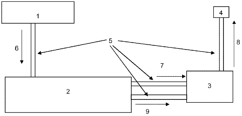
[0041] From figure 1 As can be seen in , equipment for immersion, surface treatment, or similar treatments using cryogenic liquid jets typically includes liquid nitrogen (hereinafter referred to as LN 2 ) storage container 1, such as a tank, which supplies liquid nitrogen to the compression device 2 through a liquid nitrogen supply line 6 at a low pressure—that is, a pressure of about 3 to 6 bar and a temperature of about -180° C. 2 has a compressor and an internal upstream heat exchanger for liquid nitrogen at ultra high pressure (UHP).

[0042] Thus, the compression device 2 is able to compress the LN from the storage vessel 1 2 .

[0043] Next, the LN at the first pressure (UHP) 2 Through transfer line 7 to the external downstream heat exchanger 3 where the ultra-high pressure LN is cooled with liquid nitrogen (in 9) at atmospheric pressure 2 UHP liquid nitrogen is thus usually obtained.

[0044] This leads to LN 2 At a pressure (UHP) generally above 1000 bar, general...


PUM


Abstract

The invention relates to working equipment, particularly for heat treatment, pickling, or the like, implementing high pressure liquid jets at cryogenic temperatures including a rotary or swinging tool (4) comprising one or more nozzles (11) for dispensing high pressure liquid jets at cryogenic temperatures, and a motor (21) for rotating or swinging the tool (4). The motor (21) is connected to the tool (4) via a rotary transmission shaft (22) and a transmission gearbox (23) containing an internal transmission mechanism, typically with sprockets (24) or belts. The equipment further comprises means (28) for feeding dry gas, such as nitrogen or dry air, in communication with the inside of the transmission gearbox (23) designed for and capable of feeding the inside of said transmission gearbox (23) with dry gas. Said injection of gas into the transmission gearbox (23) prevents the contamination of the inside of the transmission gearbox with atmospheric impurities.

Description

technical field [0001] The invention relates to devices and methods for working with high-pressure, low-temperature fluid jets, in particular for surface treatment, rinsing (de-scaling, descaling, pickling) or scraping (peeling, dressing) coated or uncoated materials such as metal, concrete, wood, polymers and plastics or any other type of material. Background technique [0002] Currently, the surface preparation of coated or uncoated materials is mainly carried out by sandblasting, ultra-high pressure (UHP) water jets, sanders, jacks, hammers or optionally by chemical processes, in particular dipping or scraping or similar treatment. [0003] However, only so-called "dry" working methods can be used when, for example, due to severe environmental constraints, no moisture can be contained, for example in nuclear environments or chemical products. [0004] However, in some instances it is difficult to use these "drying" methods, which are very laborious or difficult to handl...

Claims


Application Information

Patent Timeline
IPC IPC(8): B24C1/00B24C3/04
CPCB05B3/02B24C3/04B24C1/003B05B3/001
Inventor C·特鲁朔J·昆塔F·里夏尔
Owner LAIR LIQUIDE SA POUR LETUDE & LEXPLOITATION DES PROCEDES GEORGES CLAUDE
Why Eureka
Try Eureka