
Double-cylinder multistrip single-stage vacuum extruder

A vacuum extruder, single-stage technology, applied in the field of brick and tile machinery manufacturing, can solve the problems of increased power bearing, increased difficulty in forming the machine mouth, small output, etc., and achieves the effect of improving air tightness

Inactive Publication Date: 2012-04-04
程永科
View PDF4 Cites 2 Cited by
  • Summary
  • Abstract
  • Description
  • Claims
  • Application Information

AI Technical Summary

Problems solved by technology

[0003] At present, in the extrusion situation of brick and tile extruder with single mud cylinder and single reamer in our country, the conveying capacity of the reamer has a great relationship with its diameter. Under the condition of constant screw pitch and rotating speed of the reamer, the only way to increase the conveying capacity is to increase its diameter. , but the increase in diameter will double the power bearing, and will also increase the difficulty of forming the die
At the same time, the traditional brick making machine has a single clay cylinder and a single extrusion, which has a small output and high energy consumption.

Method used


Image

  • Double-cylinder multistrip single-stage vacuum extruder
  • Double-cylinder multistrip single-stage vacuum extruder
  • Double-cylinder multistrip single-stage vacuum extruder

Examples


Embodiment Construction

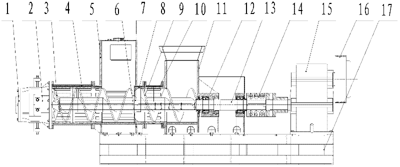
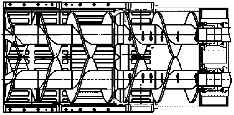
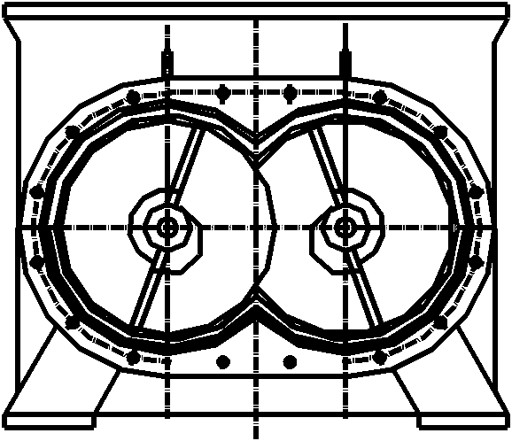
[0018] Such as Figure 1-3 A specific embodiment of the present invention is given, a double-cylinder multi-strip single-stage vacuum extruder, which consists of a double machine port 1, a machine head 2, a double reamer 3, a double mud cylinder 4, a vacuum chamber 5, and a mud adding box Base 6, outer taper sleeve 7, inner taper sleeve 8, double Hough reamer 9, Hough cylinder 10, blanking box 11, bearing group 12, double main shaft 13, coupling 14, reducer 15 and pneumatic clutch 16 It is formed and all components are located on the chassis 17. A motor drives a reducer 15 with double output shafts. The double output shafts of the reducer 15 drive the rotation of the double main shaft 13 through the coupling 14, and the double main shaft 13 is connected by the bearing group 12. The double Huff reamer 9, the double Huff reamer 9 is connected with the double reamer 3 through the inner cone sleeve 8 and the outer cone sleeve 7 to compress and extrude the mud, the double reamer 3 ...


PUM


Abstract

The invention belongs to a double-cylinder multistrip single-stage vacuum extruder in a building machinery, which is formed by double machine openings, a machine head, double reamers, double pug cylinders, a vacuum chamber, a pug addition tank base, an outer taper sleeve, an inner taper sleeve, double half reamers, a half cylinder, a blanking tank, a bearing pack, double spindles, a coupling, a speed reducer and a pneumatic clutch. All components are positioned on an underframe. The speed reducer with double output shafts is driven by a motor. The double output shafts of the speed reducer drive the double spindles to rotate by the coupling. The double spindles are connected with the double half reamers through the bearing pack. The double half reamers are connected with the double reamers through the inner taper sleeve and the outer taper sleeve to compress and extrude pug. The double reamers are positioned in the double pug cylinders and the outlet ends of the double pug cylinders are sequentially connected with the machine head and the double machine openings. The vacuum chamber is directly arranged between the double pug cylinders and the half cylinder and is positioned on the double pug cylinders. The blanking tank is arranged on the half cylinder. The double pug cylinders are horizontally arranged side by side. The center distance of the two pug cylinders is equal to the diameters of the reamers. The double spindles take relative rotating motion under the drive of the speed reducer, so that the two reamers also take relative rotating motion under the action of the spindles and materials in the vacuum chamber can be smoothly conveyed into the double pug cylinders without generating the pug return phenomenon.

Description

technical field [0001] The invention belongs to the field of brick and tile machinery manufacturing, in particular to a mud extruding device. Background technique [0002] The land area in our country is decreasing day by day, the country emphasizes cherishing the land, and the policy of wall reform in our country has changed from "forbidden" in the past to "no sticking" in recent years, energy saving and emission reduction, and now low carbon. Higher requirements. Equipment must be energy-efficient, and products must be environmentally friendly. The production of high-quality heat-preserving sintered bricks and sintered heat-insulating blocks is the main task of the brick and tile machinery and equipment industry. [0003] At present, in the extrusion situation of brick and tile extruder with single mud cylinder and single reamer in our country, the conveying capacity of the reamer has a great relationship with its diameter. Under the condition of constant screw pitch and...

Claims


Application Information

Patent Timeline
Patent Type & Authority Applications(China)
IPC IPC(8): B28B3/22
Inventor 程永科程玉全段拉勋王安湖赵智军汝永其安文州焦小婷
Owner 程永科
Learn More