
Clamping grinding device for steel sample and method

A chuck and fixture technology, which is applied in the field of inspection and testing equipment, can solve problems affecting the accuracy of analysis results, steel samples falling off and splashing and hurting people, easy to fall off and splashing and hurting people, etc., so as to reduce sandpaper consumption, improve operation efficiency, and eliminate safety hazards. hidden effect

Active Publication Date: 2012-04-04
ANGANG STEEL CO LTD
View PDF4 Cites 6 Cited by
  • Summary
  • Abstract
  • Description
  • Claims
  • Application Information

AI Technical Summary

Problems solved by technology

And these two kinds of clamping and grinding methods all have certain defects.
The first hand-holding method is mainly low in efficiency, and the labor intensity of the workers is high, and it is easy to scratch the fingers if a little careless; and the steel sample is easy to fall off and splash and hurt people during grinding, and the safety is poor.
The second magnet adsorption method, due to the adsorption effect of the magnet, makes the ground iron filings adhere to the steel sample, contaminates the steel sample, and affects the accuracy of the analysis results; and in the case of a small contact area or insufficient magnetic force of the magnet , the steel sample will also fall off and splash and hurt people during grinding

Method used


Image

  • Clamping grinding device for steel sample and method
  • Clamping grinding device for steel sample and method
  • Clamping grinding device for steel sample and method

Examples


Embodiment Construction

[0030] Below, the present invention will be further described in conjunction with the accompanying drawings.

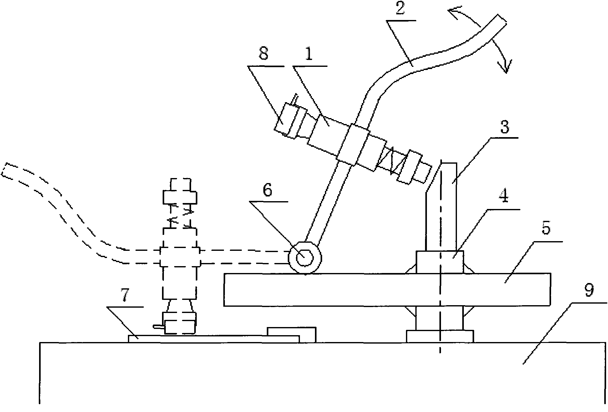
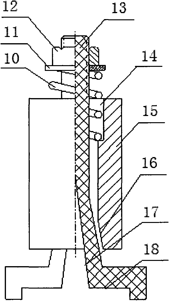
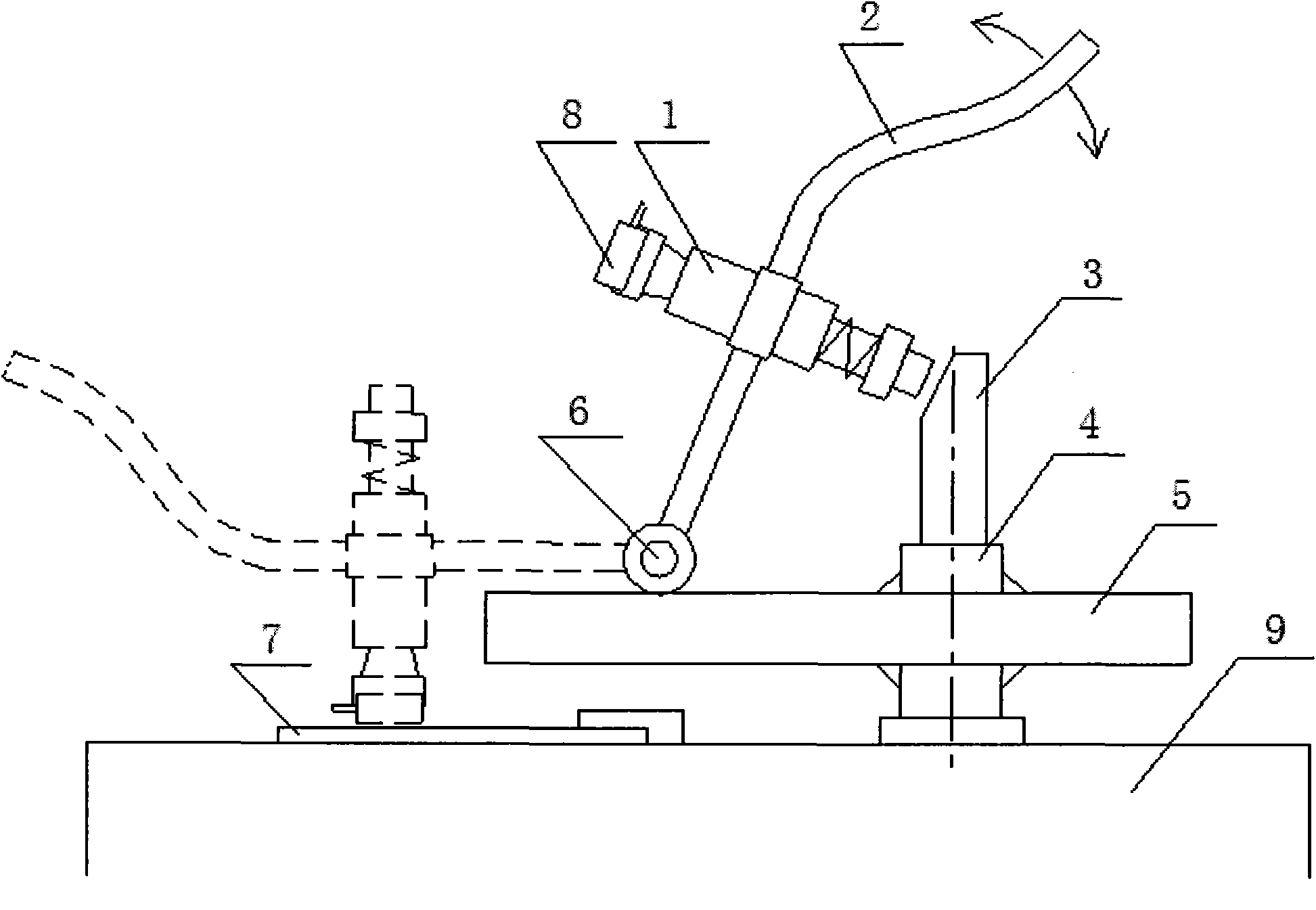
[0031] Depend on figure 1 It can be seen that the steel sample clamping and grinding device of the present invention is mainly composed of a clamp 1, a turning lever 2, a meeting head 3, a rotating shaft 4, a support plate 5, a hinge shaft 6 and a sample grinding machine platform 9. The support plate 5 is movably connected to the right side of the upper surface of the sample mill platform 9 through the rotating shaft 4, and the supporting plate 5 can rotate horizontally with the rotating shaft 4 as an axis. A meeting head 3 is arranged on the upper end of the rotating shaft 4, and the top of one side of the meeting head 3 has an inclined surface; a clamp 1 is fixed on the straight bar section in the middle of the curved turning bar 2, and the lower end of the turning bar 2 is hinged on the support plate 5 through the hinge shaft 6 On the left side of the upper surfac...


PUM

PropertyMeasurementUnit
widthaaaaaaaaaa
diameteraaaaaaaaaa
depthaaaaaaaaaa

Abstract

The invention provides a clamping grinding device for a steel sample and a method. According to the invention, a support plate is movably connected with a platform of a grinding machine through a rotating shaft, the upper end of the rotating shaft is provided with a stop with an inclined plane, and the lower end of an overturning rod equipped with a clamp is hinged onto the support plate; when the overturning rod upturns, the clamp on the overturning rod crashes with the stop, and a slide bar extends out and puts a steel sample to be ground into a groove of a chuck; when the overturning rod is loosened, under the action of a pressure spring, the slide bar allows the chuck to clamp the steel sample; when the overturning rod is turned down, a grinding surface of the steel sample abuts onto a sand paper, which enables the steel sample to be further locked; the steel sample is ground until the steel sample accords with the standard, the overturning rod is turned up, the chuck is loosened,and the steel sample is taken down and sent for inspection. The device provided in the invention has the advantages of a little investment, fast action and a simple structure, can be made by oneself and firmly clamp steel samples, and enables the clamping grinding speed of steel samples to be substantially accelerated, labor intensity of workers to be alleviated, operability to be improved, consumption of sand paper to be reduced, the problem of injury of people caused by falling off of steel samples to be eliminated and accuracy of component analysis of steel samples to be enhanced.

Description

technical field [0001] The invention belongs to the field of inspection and testing instruments, and in particular relates to a clamping and grinding device for steel samples in a steelmaking plant and a clamping and grinding method thereof. Background technique [0002] Every time the steelmaking plant finishes tapping the converter, the molten steel should be sampled and then sent to the laboratory for component analysis. Since a layer of iron oxide is formed on the surface of the steel sample when it is cooled, the accuracy of the analysis results will be affected if the composition analysis of this steel sample is carried out. Therefore, the oxide layer formed on the surface of the steel sample must be treated, that is, the sample needs to be ground, which is an important step before the steel sample is analyzed. [0003] At present, there are mainly two methods for steel sample grinding in domestic steelmaking plants: one is the simple hand-held sample clamping method,...

Claims


Application Information

Patent Timeline
Patent Type & Authority Applications(China)
IPC IPC(8): G01N1/28G01N1/32B24B19/00
Inventor 马忠仁梁祥远李丹吴长宽
Owner ANGANG STEEL CO LTD
Learn More