Solar cell plate, solar cell string and solar cell assembly

A technology of solar cells and solar cells, which is applied to electrical components, circuits, photovoltaic power generation, etc., can solve the problems of complex procedures and high manufacturing costs, achieve the effect of small shading area, reduce processing procedures, and maintain photoelectric conversion efficiency

Inactive Publication Date: 2012-04-04
JIANGXI SAI WEI LDK SOLAR HI TECH CO LTD
View PDF8 Cites 8 Cited by
  • Summary
  • Abstract
  • Description
  • Claims
  • Application Information

AI Technical Summary

Problems solved by technology

[0004] However, this solar cell also has the following disadvantages: because there are many fine grid lines 94 on the front of the cell, it is necessary to process a l

Method used


Image

  • Solar cell plate, solar cell string and solar cell assembly
  • Solar cell plate, solar cell string and solar cell assembly
  • Solar cell plate, solar cell string and solar cell assembly

Examples


Embodiment 1

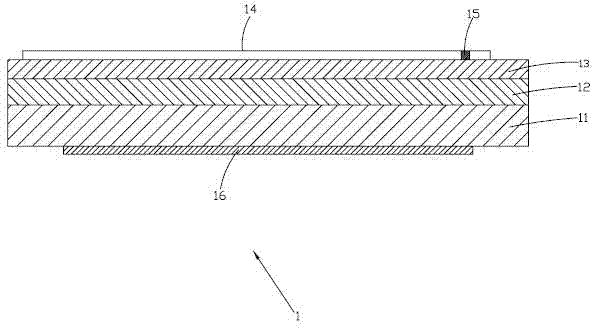
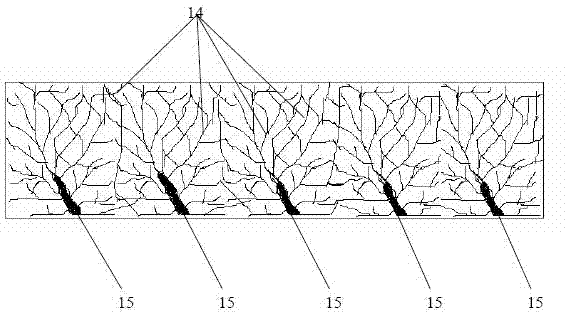
[0031] Such as figure 2 and image 3 As shown, a solar cell 1 provided in Embodiment 1 of the present invention has a length of 3-40 cm, a width of 1-15 cm, and a thickness of 0.08-2 mm. The solar cell 1 includes silicon wafers stacked in sequence 11. Diffusion layer 12 and anti-reflection film 13. The upper surface of anti-reflection film 13 is provided with several thin grid lines 14 for conducting current and at least one main grid line 15 for conducting current and having a small light-shielding area. Thin grid lines 14 are intersected or combined to form a pattern of a certain shape (such as rhombus, rectangle, dendritic or mesh shape), and each of the thin grid lines 14 is connected to at least one main grid line 15, and the silicon At least one back electric field 16 is provided on the lower surface of the sheet 11 . Wherein, the thin grid lines 14 and the main grid lines 15 are negative electrodes of the solar cell 1 , and the back electric field 16 is the positive ...

Embodiment 2

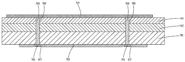
[0044] Such as Figure 5 and Figure 6 As shown, a solar cell 2 provided by Embodiment 2 of the present invention has a length of 3-40 cm, a width of 1-15 cm, and a thickness of 0.08-2 mm. The solar cell 2 includes silicon wafers stacked in sequence 21. Diffusion layer 22 and anti-reflection film 23. The upper surface of anti-reflection film 23 is provided with several thin grid lines 24 for conducting current and at least one main grid line 25 for conducting current and having a small light-shielding area. A plurality of thin grid lines 24 are intersected or combined to form a pattern of a certain shape (such as rhombus, rectangle, dendritic or mesh shape), and each thin grid line 24 is connected to at least one main grid line 25. At least one back electrode 26 and a back electric field 27 are provided on the lower surface of the silicon wafer 21 . Wherein, the thin grid lines 24 and the main grid lines 25 are negative electrodes of the solar cell 2 , and the back electrode...


PUM

PropertyMeasurementUnit
Lengthaaaaaaaaaa
Widthaaaaaaaaaa
Thicknessaaaaaaaaaa

Abstract

The invention relates to a solar cell plate. A thin grid line and a main grid line are disposed on the front surface of the solar cell plate at the same time, and the current generated by the solar cell plate is converged to the main grid line with small sun shading area from the thin grid line and then are transmitted to back electrode or back electric field on the back surface of another adjacent solar cell plate from the main grid line. The main grid line has small sun shading area, so higher current can be generated; each thin grid line is connected with at least one main grid line, and the current generated by the cell plate can be transmitted to the main grid line from the shortest thin grid line, so that low electric loss on the electrode is realized and electric energy using ratio of the cell plate is improved. The arrangement of conductive hole on the solar cell plate is avoided, working procedure of processing the conductive hole is reduced, filling of expensive conductive paste and complicated electrode wire connection on the back surface of the cell plate are not needed, and photoelectric conversion efficiency equivalent to that of high-efficiency solar cell is kept while manufacturing cost is reduced. The invention also provides a solar cell string and a solar cell assembly using the solar cell plate.

Description

technical field [0001] The invention belongs to the field of photovoltaic or semiconductor, and in particular relates to a solar battery sheet, a solar battery string and a solar battery module using the solar battery sheet. Background technique [0002] Such as figure 1 As shown, the existing solar cells (such as high-efficiency MWT (Metal Wrap Through) cells) include a silicon wafer 91, a diffusion layer 92 and an anti-reflection film 93 stacked in sequence. Each thin grid line 94 is arranged parallel to each other on the thin grid lines 94 for conducting current. At least one positive electrode 95 and at least one negative electrode 96 are provided on the lower surface of the silicon chip 91, and an insulating groove is passed between the positive electrode 95 and the negative electrode 96. 97 isolation, on the silicon wafer 91, the diffusion layer 92 and the anti-reflection film 93, there is at least one through conductive hole 98, the conductive hole 98 is filled with ...

Claims


Application Information

Patent Timeline
IPC IPC(8): H01L31/0224H01L31/042
CPCY02E10/52Y02E10/50
Inventor 中野研吾孙李媛
Owner JIANGXI SAI WEI LDK SOLAR HI TECH CO LTD
Why Eureka
Try Eureka