Eureka AIR delivers breakthrough ideas for toughest innovation challenges, trusted by R&D personnel around the world.

Microplasma source and sterilization system including the same

一种微等离子体、灭菌系统的技术,应用在离子体产生装置领域,能够解决难以覆盖、困难性提升、灭菌的成效受制待处理物几何形状等问题,达到增加使用安全性、利于操作的效果

Inactive Publication Date: 2012-04-04
廖峻德
View PDF6 Cites 22 Cited by
  • Summary
  • Abstract
  • Description
  • Claims
  • Application Information

AI Technical Summary

Problems solved by technology

However, the above-mentioned DBD plasma is still limited in use, because most of the medical devices have irregular shapes, but it is difficult for the DBD plasma to cover all exposed surfaces of the above-mentioned medical devices, or it is difficult to act on some of the aforementioned medical devices. The bacteria hidden in these crevices, therefore, the effectiveness of sterilization is limited by the geometry of the object to be treated
On the other hand, hidden and residual bacteria are usually in a humid environment, such as in an aqueous solution, so it is necessary to use a sterilization technique that can ensure complete sterilization in an aqueous solution, but if DBD plasma is used to sterilize in an aqueous solution Bacteria, the difficulty will be greatly increased

Method used


Image

  • Microplasma source and sterilization system including the same
  • Microplasma source and sterilization system including the same
  • Microplasma source and sterilization system including the same

Examples


Embodiment 1

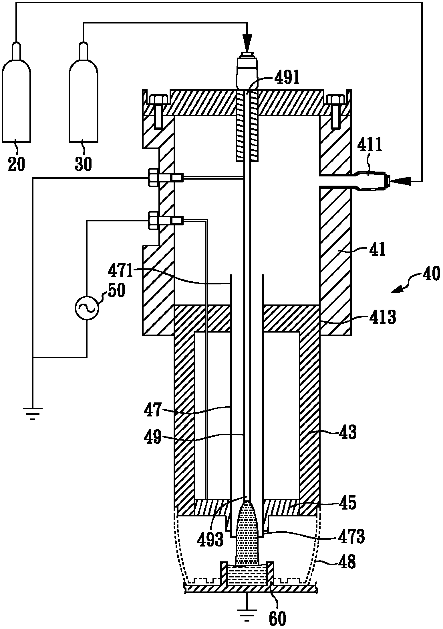
[0055] figure 1 is a schematic diagram of the micro-plasma generating device of this embodiment. Such as figure 1 As shown, the micro plasma generation device of the present invention mainly includes: a first gas storage unit 20 , a second gas storage unit 30 , a micro plasma generation unit 40 , and a power supply unit 50 .

[0056] In the present invention, the first gas storage unit 20 is used to store a first gas, and the second gas storage unit 30 is used to store a second gas. In this embodiment, the first gas is used as a plasma excitation gas, such as argon, and the second gas is used as a reactive gas, such as oxygen.

[0057] The micro-plasma generating unit 40 mainly includes: a gas transmission cavity 41, which has a first inlet port 411 and a first outlet port 413, wherein the first inlet port 411 is connected to the first gas storage unit 20 and Input the first gas; a heat dissipation protection cavity 43, which has the functions of heat dissipation and protec...

Embodiment 2

[0061] The micro plasma sterilization system of the present embodiment, as figure 1 As shown, it mainly includes: a first gas storage unit 20 , a second gas storage unit 30 , one or a plurality of micro plasma generation units 40 , and a power supply unit 50 . The structure of the micro-plasma sterilizing system of this embodiment is substantially the same as that of Embodiment 1, and in addition to the above-mentioned components, an additional sample tank 60 may be provided as required for accommodating solid samples or liquid samples.


PUM


Abstract

A microplasma source and a sterilization system including the same are disclosed. The microplasma source includes: a microplasma-generating unit including: a gas transmission chamber having a first inlet and a first outlet wherein the first inlet is used to import a first gas; a protection and heat dissipation chamber of which a side is connected to the inner wall of the first outlet; a dielectric inner tube having a second inlet and a second outlet and penetrating through the protection and heat dissipation chamber, wherein the second inlet is communicated to the gas transmission chamber; an electrode arranged outside at the second outlet and located in the protection and heat dissipation chamber; and a hollow metal tube disposed in the gas transmission chamber and the dielectric inner tube and having a third inlet and a third outlet, wherein the third inlet is used to import a second gas.

Description

technical field [0001] The invention relates to a micro-plasma generating device, in particular to a micro-plasma generating device and a micro-plasma sterilizing system suitable for sterilization. Background technique [0002] For reusable medical appliances, such as: when sterilizing surgical or dental appliances, it is necessary to ensure that all microorganisms attached to these appliances, whether bacteria, fungi or viruses, need to be completely removed to prevent the next Patient is infected with any possibility. However, currently known sterilization methods, such as high heat and high pressure sterilization, application of chemical bactericides such as ethylene oxide, or physical radiation irradiation, are likely to be harmful to the processed samples. cause some degree of damage or destruction. Therefore, in recent years, large-scale medical institutions have begun to adopt low-temperature and low-pressure plasma sterilization methods, that is, in a vacuum state,...

Claims


Application Information

Patent Timeline
Patent Type & Authority Applications(China)
IPC IPC(8): H05H1/30A61L2/14
CPCA61L2/14H05H1/48H05H2245/1225H05H1/2406H05H2245/36
Inventor 廖峻德翁志强陈信宏林东毅
Owner 廖峻德
Why Eureka
Eureka Blog
Learn More