
Power head of rear cover-plate type rotary drilling rig and installation method thereof

A technology of a rotary drilling rig and an installation method, which is applied to rotary drilling rigs, drilling equipment and methods, percussion drilling, etc., and can solve problems such as difficulty in increasing the output torque, smaller space in the main box, and poor rigidity, and achieve The reduction ratio is increased, the output torque is large, and the effect of large output torque

Inactive Publication Date: 2012-04-11
林龙海
View PDF6 Cites 5 Cited by
  • Summary
  • Abstract
  • Description
  • Claims
  • Application Information

AI Technical Summary

Problems solved by technology

The power head of this rotary drilling rig in the prior art has a dual hydraulic motor drive type and a single hydraulic motor drive type, but no matter whether it is a dual hydraulic motor drive or a single hydraulic motor drive rotary drilling rig power head, there are deficiencies. : The output torque is difficult to increase and the rigidity is poor
In order to achieve a stable connection, the side wall of the main box is required to have a certain thickness, so that the side wall of the main box can open screw holes and meet the rigidity requirements. However, too thick side walls of the main box will cause The available space becomes smaller, so that the processing size of the driven gear is limited, so that the output torque of the entire power head cannot be increased
In addition, the gear box adopts the upper cover plate or the lower cover plate type, which will also lead to poor rigidity of the gear box body, and the use is not reliable enough

Method used


Image

  • Power head of rear cover-plate type rotary drilling rig and installation method thereof
  • Power head of rear cover-plate type rotary drilling rig and installation method thereof
  • Power head of rear cover-plate type rotary drilling rig and installation method thereof

Examples


Embodiment Construction

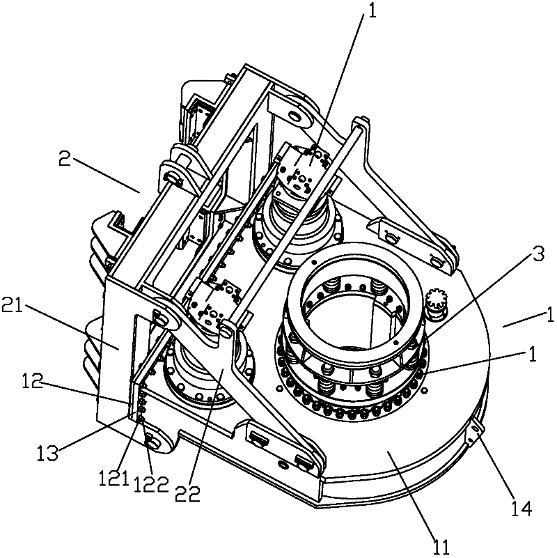
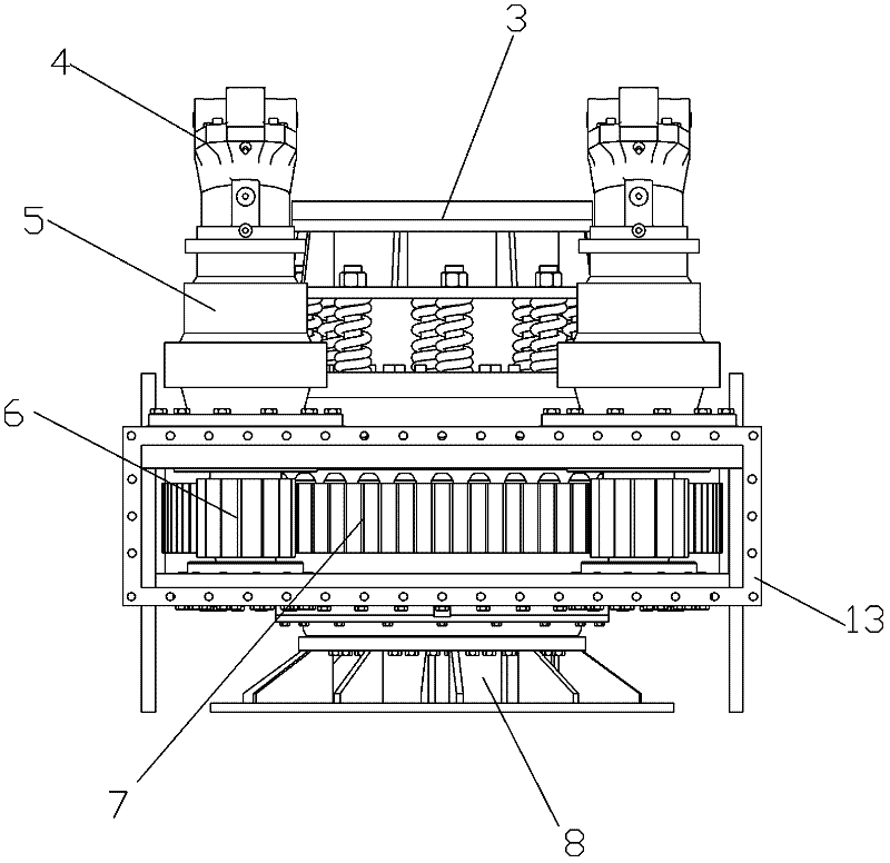
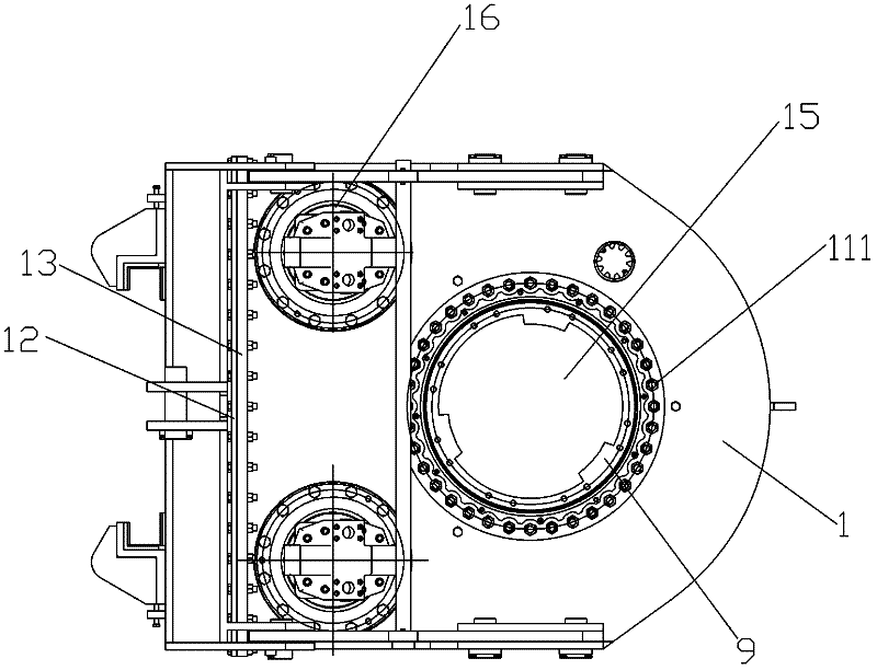
[0031] Examples, see Figure 1 to Figure 4 As shown, the power head of a back cover type rotary drilling rig of the present invention is a double hydraulic motor drive type, which includes a carriage device 2, two hydraulic motors 4, two planetary reducers 5, two active Gear 6, a driven gear 7, a gear housing 1, a drive sleeve 9, a buffer device 3 and a pressure plate device 8. The gear case 1 comprises a rear cover plate 12 and a main case 11 with an integral structure and an opening on the rear side. The top end of the main case 11 is provided with a first mounting hole 15 and two holes for installing the driving gear. A third mounting hole 16, correspondingly, the bottom end surface of the main box body 11 is provided with a second mounting hole 17 coaxial with the first mounting hole 15 and two coaxial with the two third mounting holes 16 respectively The fourth installation hole 18 , wherein the diameter of the second installation hole 17 is larger than the diameter of t...


PUM


Abstract

The invention discloses a power head of a rear cover-plate type rotary drilling rig and an installation method thereof. The power head comprises a carriage device, a hydraulic motor, a planetary reducer, a driving gear, a driven gear, a gearbox casing, a drive bushing, a buffer device and a disk-pressing device, wherein the gearbox casing comprises a rear cover-plate and a main casing, the main casing is in an integral structure and the rear side of the main casing is provided with an opening, the top surface of the main casing is provided with a first installing hole and a third installing hole, the bottom surface of the main casing is provided with a second installing hole and a fourth installing hole, and the diameter of the second installing hole is greater than that of the first installing hole; the driven gear is embedded in the main casing from the opening on the rear side of the main casing; the rear cover-plate is locked and fixed at the opening on the rear side of the main casing; and the driven gear is installed by using a pre-designed tool, and has the characteristics of novel process, convenience and rapidness in installation, and the like. By using the power head disclosed by the invention, after a rear cover-plate type structure is adopted, the stiffness of the gearbox casing is increased and a larger output torque is acquired.

Description

technical field [0001] The invention relates to a back cover type rotary drilling rig power head, in particular to a back cover type rotary drilling rig power head with good rigidity and large output torque and an installation method thereof. Background technique [0002] At present, the power head of the rotary drilling rig in the prior art is mainly composed of a carriage device, a hydraulic motor, a planetary reducer, a driving gear, a driven gear, a gear box, a driving sleeve, a buffer device, and a pressure plate device. The hydraulic motor transmits power to the planetary reducer, then to the driven gear through the driving gear, and finally to the drill pipe of the rotary drilling rig through the drive sleeve connected with the driven gear. The power head of this rotary drilling rig in the prior art has a dual hydraulic motor drive type and a single hydraulic motor drive type, but no matter whether it is a dual hydraulic motor drive or a single hydraulic motor drive r...

Claims


Application Information

Patent Timeline
IPC IPC(8): E21B3/02F16H57/02F16H57/023F16H57/031
Inventor 林龙海
Owner 林龙海
Features
  • Generate Ideas
  • Intellectual Property
  • Life Sciences
  • Materials
  • Tech Scout
  • Unparalleled Data Quality
  • Higher Quality Content
  • 60% Fewer Hallucinations
Learn More