Reciprocating percussive-rotary drilling tool

A rotary drilling and reciprocating technology, which is applied in the field of geological exploration hole drilling engineering, can solve the problems of drill string torsional vibration, drill sticking, drill bit, and adverse effects on the service life of drill string supporting parts, so as to improve rock breaking efficiency and improve ROP and the effect of reducing the stick-slip phenomenon

Inactive Publication Date: 2012-04-18
SOUTHWEST PETROLEUM UNIV
View PDF6 Cites 10 Cited by
  • Summary
  • Abstract
  • Description
  • Claims
  • Application Information

AI Technical Summary

Problems solved by technology

[0002] At present, most of the drilling tools used in oil fields can only provide axial impact force or circumferential torque. For hard formations or abrasive formations, when the drilling tools only provide axial impact force, the penetration depth of the drill bit is not enough. , the ROP needs to be improved; and when the drilling tool only provides circumferential torque, it often lacks enough torque to destroy the formation, so that the drill bit stops rotating instantly, and stick-slip and sticking occur. At this time, the drill string will be like clockwork. The same tightening, the torque is accumulated and released quickly, resulting in torsional vibration of the drill string, and at the same time, the drill bit will also be subject to higher impact loads, which will adversely affect the service life of the drill bit and drill string accessories.

Method used


Image

  • Reciprocating percussive-rotary drilling tool
  • Reciprocating percussive-rotary drilling tool
  • Reciprocating percussive-rotary drilling tool

Examples


Embodiment Construction

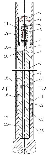
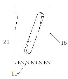
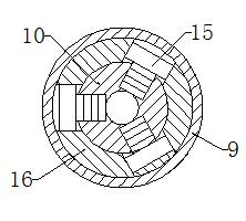
[0011] Such as figure 1 , figure 2 , image 3 As shown, a reciprocating impact rotary drilling tool of the present invention is composed of a flow controller 1, an upper joint 2, an automatic valve device 19, a casing 9, a mandrel 10, a rotating device 16, and a load-bearing joint 17. Its structural features are: the upper joint 2 is connected to the upper part of the shell 9 through threads, and a flow controller 1 is installed inside; the automatic valve device 19 is installed in the upper joint 2, and the automatic valve device 19 is composed of the valve stroke calibration device 3 and the valve stem 4 , a valve body 5, a valve head 6, and a valve spring 14, which together with the upper end surface of the shell 9 and the mandrel 10 form a variable volume chamber 18; There is a seal 7 between the two; there are three spiral grooves 21 on the rotating device 16, and there is a unidirectional lower pawl surface 11 on the lower end surface, and the cylindrical follower 15 ...


PUM


Abstract

The invention discloses a percussive-rotary drilling tool which is used for providing reciprocating percussion and torque simultaneously during well drilling and can improve drilling efficiency and mechanical drilling rate, and reduce drilling cost. The technical scheme is that: a flow controller is arranged in an upper joint and an automatic valve device below the flow controller is connected with an inner hole of the upper joint through a thread; the automatic valve device, a shell, and an upper end face of a central spindle form a cavity with a variable volume; a flow channel is formed in the middle of the central spindle; a sealing member is arranged between an outer wall of the upper end of the central spindle and an inner wall of the shell; a thread of the lower part of the central spindle is used for connecting a drill bit; and a rotation device is provided with a spiral groove, cylinder followers of the rotation device are arranged on the central spindle, and the bottom of the rotation device is provided with an unidirectional lower pawl surface which is matched with an unidirectional upper pawl surface on the upper part of a bearing joint. The percussive-rotary drilling tool has a simple structure, is suitable for well repairing and drilling operation, and can provide torque and percussion energy, reduce the phenomenon that the drilling bit is sticky and slippery, accelerate mechanical drilling rate, improve drilling efficiency and reduce drilling cost.

Description

technical field [0001] The invention relates to a rotary percussion drilling tool capable of simultaneously providing reciprocating impact and torque during drilling, which is suitable for oil and gas drilling engineering and workover services, and can also be used for geological exploration hole drilling engineering. Background technique [0002] At present, most of the drilling tools used in oil fields can only provide axial impact force or circumferential torque. For hard formations or abrasive formations, when the drilling tools only provide axial impact force, the penetration depth of the drill bit is not enough. , the ROP needs to be improved; and when the drilling tool only provides circumferential torque, it often lacks enough torque to destroy the formation, so that the drill bit stops rotating instantly, and stick-slip and sticking occur. At this time, the drill string will be like clockwork. The same tightening, the torque is accumulated and released quickly, resu...

Claims


Application Information

Patent Timeline
Patent Type & Authority Applications(China)
IPC IPC(8): E21B6/00
Inventor 祝效华李佳南石昌帅童华
Owner SOUTHWEST PETROLEUM UNIV
Why Eureka
Try Eureka