Dewatering apparatus and oil-water cyclone separator of pipe type distributor oil-water separator

A technology of oil-water separator and deflector, which is applied in the direction of the device, the swirl device, the separation method, etc. where the axial direction of the swirl flow remains unchanged, and can solve the fluctuation of the operating parameter inlet condition, limit the processing capacity, and the outflow of the oil phase and other problems, to achieve the effect of improving oil-water separation efficiency, good adaptability, and small space occupation

Active Publication Date: 2012-04-25
INST OF MECHANICS - CHINESE ACAD OF SCI
View PDF8 Cites 11 Cited by
  • Summary
  • Abstract
  • Description
  • Claims
  • Application Information

AI Technical Summary

Problems solved by technology

The disadvantage is that once the operating parameters are set improperly or the inlet conditions fluctuate, part of the oil phase may flow out from the bottom flow port by the water phase an

Method used


Image

  • Dewatering apparatus and oil-water cyclone separator of pipe type distributor oil-water separator
  • Dewatering apparatus and oil-water cyclone separator of pipe type distributor oil-water separator
  • Dewatering apparatus and oil-water cyclone separator of pipe type distributor oil-water separator

Examples


Embodiment Construction

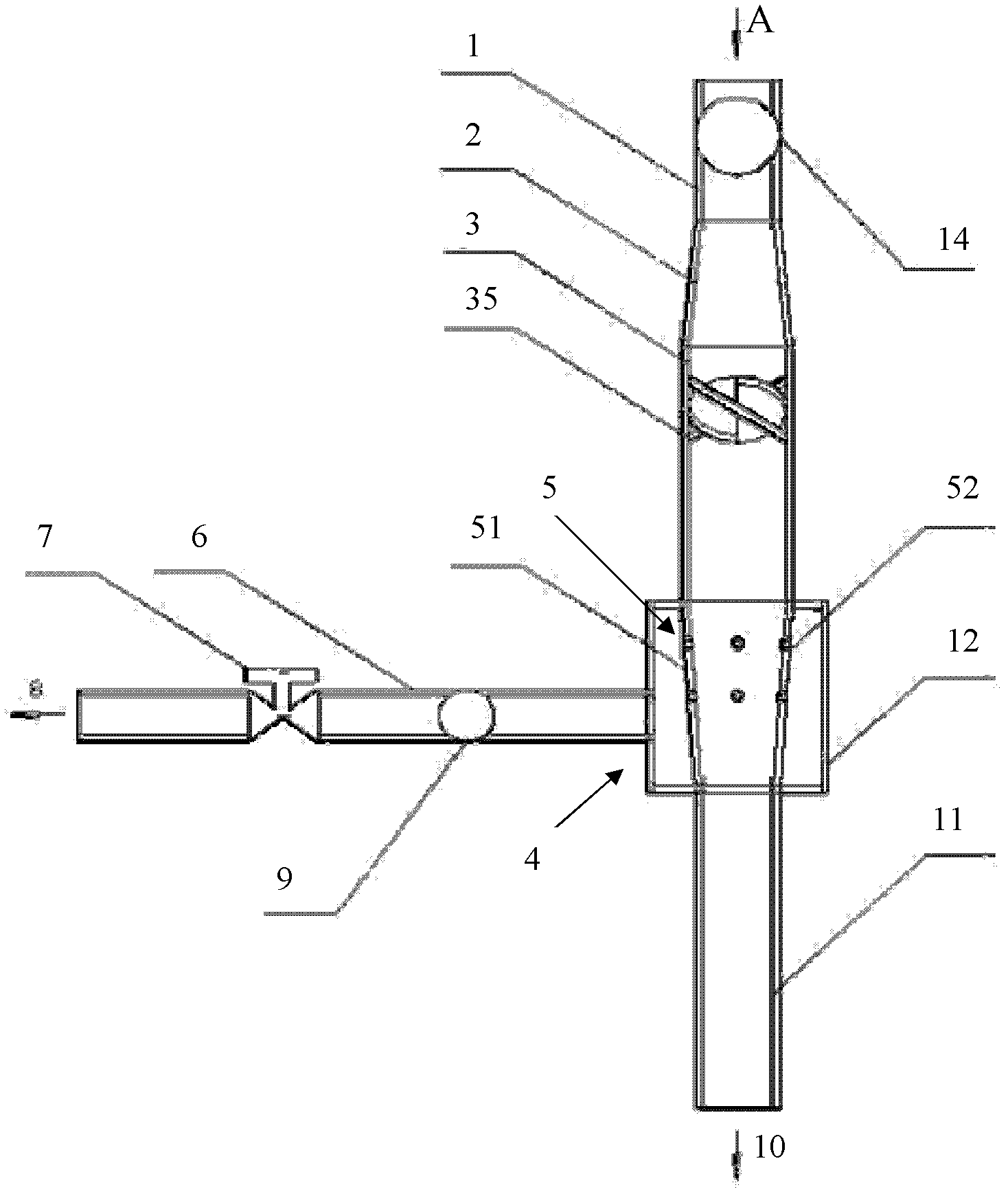
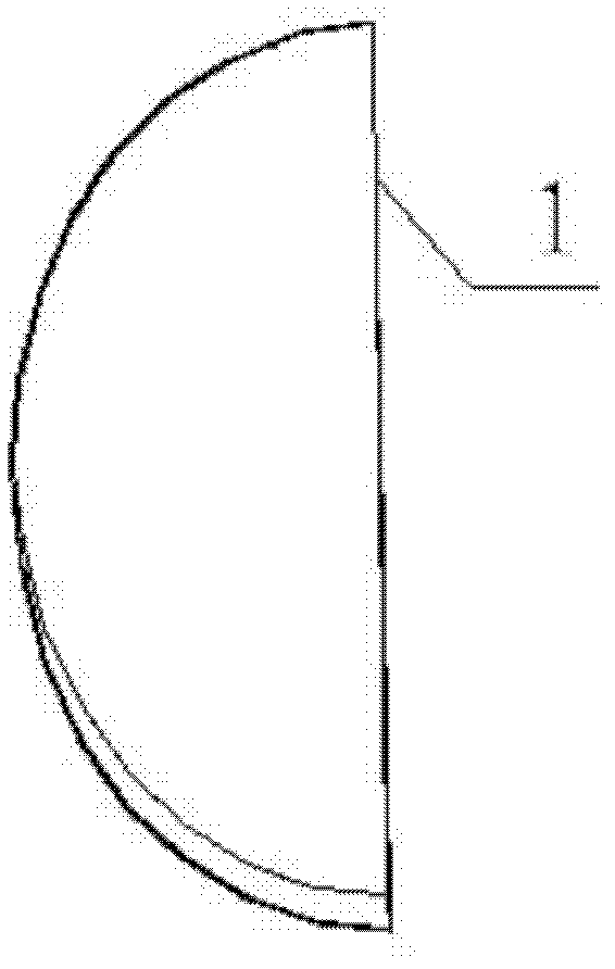
[0028] like figure 1 As shown, the present invention includes: the liquid inlet pipe section 1, the gradual expansion pipe section 2, the swirl flow generation pipe section 3 and the gradual water removal pipe section 5 connected in sequence, because the inner diameter of the swirl flow pipeline of the swirl flow generation pipe section 3 is larger than the liquid inlet pipe section The inner diameter of the pipeline of 1, therefore, the expanding pipe section 2 is set between the liquid inlet pipe section 1 and the swirl flow generation pipe section 3, and a flow meter 14 is installed on the liquid inlet pipe of the liquid inlet pipe section 1.

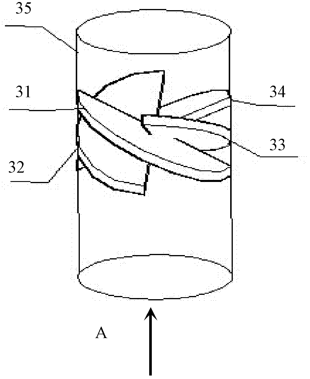
[0029] like Figure 2~3 As shown, the swirl generation pipe section 3 further includes 4 deflectors 31, 32, 33, 34 that can be fixedly and obliquely installed in the swirl pipe 35, and the deflectors 31, 32, 33, 34 are along Evenly distributed in the circumferential direction, and stacked in sequence in the axial direction of the sw...


PUM


Abstract

The invention discloses a dewatering apparatus of a pipe type distributor oil-water separator. The apparatus comprises a dewatering pipe with an oil-water inlet and an oil-water outlet. More than one set of dewatering holes are arranged on the dewatering pipe along an axial direction of the dewatering pipe. External peripheral planes of the dewatering holes are tangent with the inner wall of the dewatering pipe. The dewatering hole diameter d' is no larger than bD-calphaD, wherein b an c are constants, D is a diameter at the outlet, and alpha is an oil content at the inlet. The invention also discloses an oil-water cyclone separator. According to the invention, the external peripheral planes of the provided dewatering holes are tangent with the inner wall of the dewatering pipe, and the dewatering hole diameter d' is no larger than bD-calphaD, such that the diameters of the dewatering holes can be regulated according to the oil content, and an oil-water separating effect is improved.

Description

technical field [0001] The invention relates to a water removal device and an oil-water cyclone separator in a novel oil-water cyclone separator, in particular to a water removal device and an oil-water cyclone separator applied in an oil-water separator in an oil-water separation system downhole . Background technique [0002] With the prolongation of oilfield development time, water production continues to increase, which increases production costs. In order to reduce production costs, it has become a consensus to use downhole oil-water separators to separate water and reinject it into formations in situ. [0003] The separation principles currently used for downhole oil-water separation are mainly gravity and centrifugation. For example, the patent publication number: CN 101025080A, the method of multi-cup isoflow downhole oil-water separator to realize injection and production of high water-cut wells in the same well uses the principle of gravity. Natural sedimentation ...

Claims


Application Information

Patent Timeline
IPC IPC(8): B01D17/038
CPCB01D17/0217B04C3/06B04C2003/006E21B43/34B04C3/00
Inventor 吴应湘许晶禹史仕荧郭军张军
Owner INST OF MECHANICS - CHINESE ACAD OF SCI
Why Eureka
Try Eureka