Hydraulic control type opposed piston engine

A technology of opposed pistons and engines, which is applied to internal combustion piston engines, combustion engines, machines/engines, etc., can solve problems affecting transmission efficiency and reliability problems, and achieve good dynamic balance, fewer parts, and convenient processing Effect

Inactive Publication Date: 2012-04-25
欧益忠 +2
View PDF6 Cites 7 Cited by
  • Summary
  • Abstract
  • Description
  • Claims
  • Application Information

AI Technical Summary

Problems solved by technology

However, the number of engine revolutions ranges from hundreds to thousands of revolutions. In this way, t

Method used


Image

  • Hydraulic control type opposed piston engine
  • Hydraulic control type opposed piston engine
  • Hydraulic control type opposed piston engine

Examples


Embodiment Construction

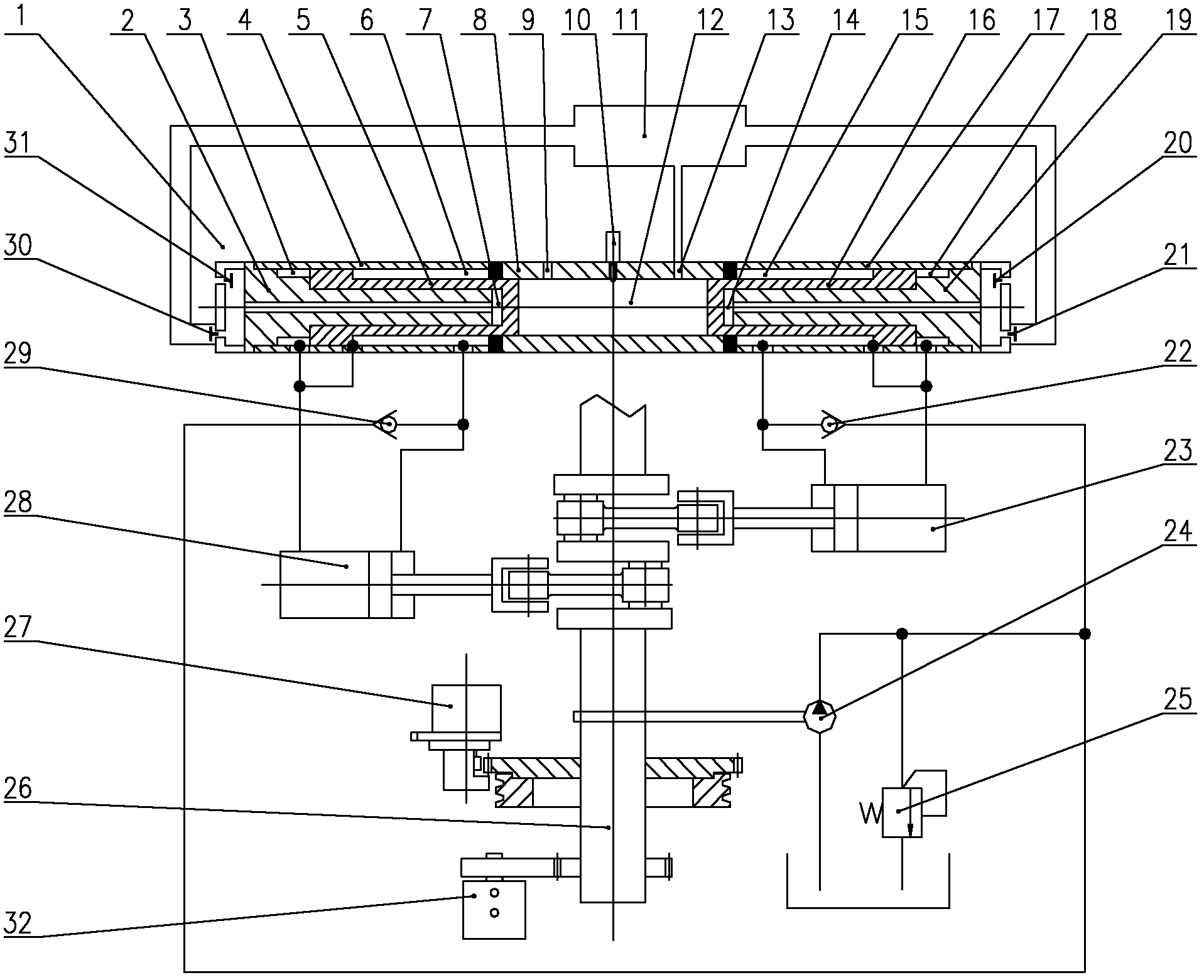
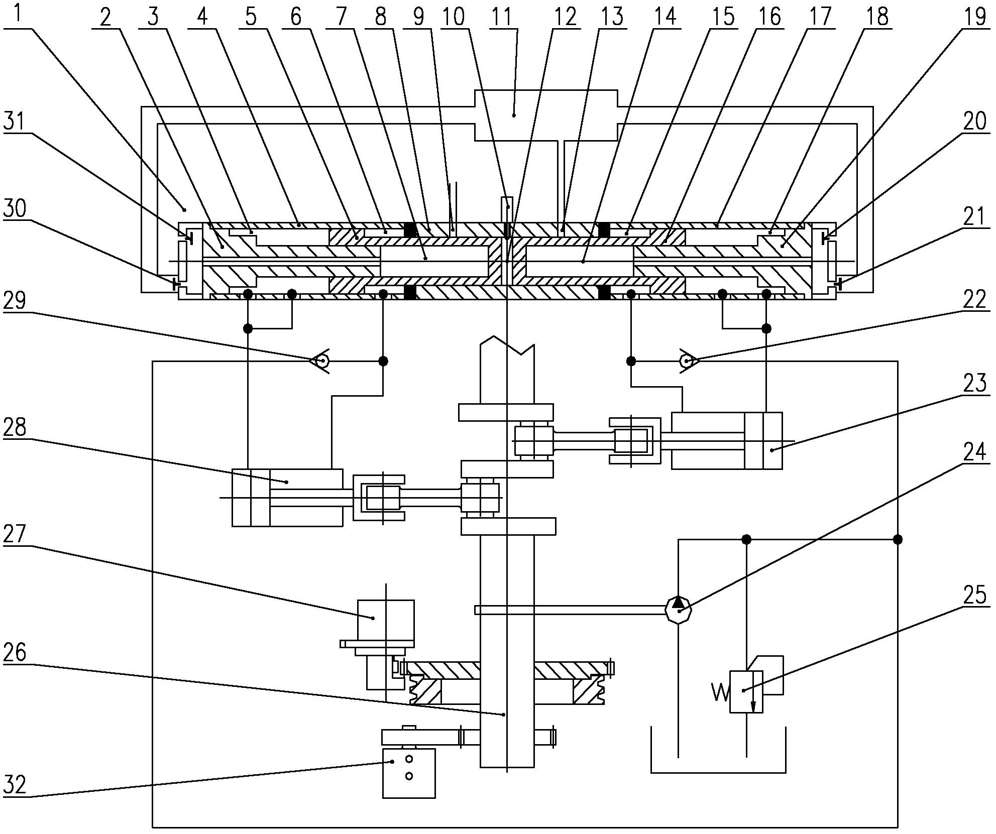
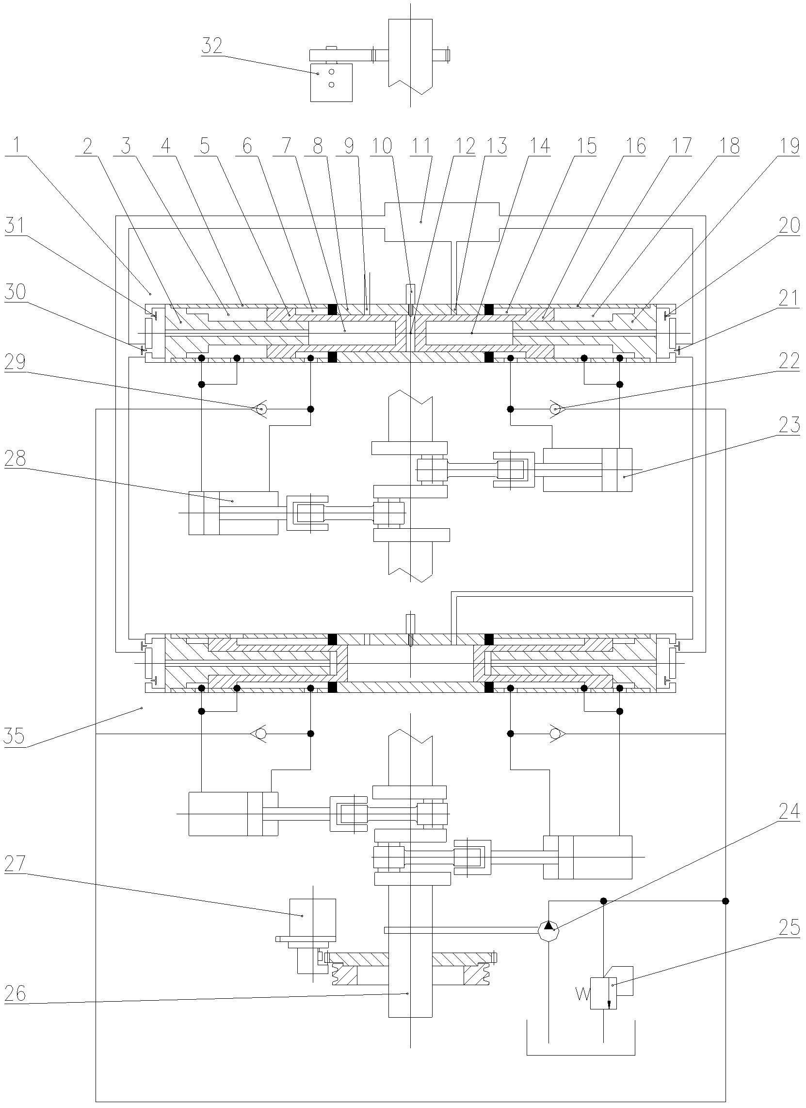
[0025] The present invention will be further described below in conjunction with the accompanying drawings and specific embodiments.

[0026] see figure 1 , figure 2 and Figure 7, the crankshaft connecting rod mechanism 26 is connected with the starting assembly 27 and the fuel injection pump assembly 32, and is provided with a group of first single-cylinder double-piston opposed hydraulic engine group 1, and the structure of the first single-cylinder double-piston opposed hydraulic engine group 1 is: The left end of the cylinder 8 is provided with a left oil cylinder 4, the left moving piston 5 is arranged in the left oil cylinder 4 and the cylinder 8, and a left oil return chamber 6 is formed between the side wall of the left moving piston 5 and the left oil cylinder 4 , the left pressure oil chamber 3 is formed between the bottom of the left moving piston 5 and the left oil cylinder 4, the right end of the cylinder 8 is provided with the right oil cylinder 17, and the r...


PUM


Abstract

The invention discloses a hydraulic control type opposed piston engine. In the scheme, each unit opposed piston component is provided with a group of opposed movable pistons, and interfaces at oil receiving ends of the pistons respectively correspond to interfaces of two groups of reciprocating positive displacement pumps on a rotating crankshaft. Changes in the rotating crankshaft and the positive displacement pumps are directly coupled onto the pistons to accurately control the movement direction of the pistons and the positions of upper dead center and lower dead center so as to respectively complete the working stroke of air intake, compression, acting expansion and expansion work and also the power output. The pistons can be controlled in a simple way to achieve the advantages of a conventional engine and a hydraulic free piston engine and overcome the defects of the conventional engine and the hydraulic free piston engine. A startup system, an oil supply system, a combustion system, a cooling system, a sealing system and other systems all adopt the existing completely mature techniques to facilitate the implementation of projects. The engine is suitable for promotion in the engine industry.

Description

technical field [0001] The present invention relates to an engine, in particular to a hydraulically controlled mobile opposed piston engine. Background technique [0002] Existing conventional engines rely on the crankshaft, piston, connecting rod, and cam valve mechanism to complete the engine's working process. It is now very perfect, but it has reached a certain working condition, such as large cylinder diameter, long stroke, high boost and high power, and the compression ratio can be achieved. Adjustment, energy saving and environmental protection and other technical indicators will be restricted by various aspects. In this field, people have made various attempts, including the famous triangular piston rotary engine, but because of its special curve, it has caused difficulties in production and maintenance, especially the sealing has not been fundamentally solved. So it has not been widely promoted so far. [0003] Can the engine structure be simplified such as cancel...

Claims


Application Information

Patent Timeline
IPC IPC(8): F02B75/28F02B75/32F02B29/06
CPCY02T10/146F02B75/282F02B75/28F02B75/32
Inventor 欧益忠张广益张琼美
Owner 欧益忠
Why Eureka
Try Eureka