Sinusoidal flow generating device

A flow generation, sinusoidal technology, applied in the direction of machine/engine, liquid variable capacity machinery, multi-cylinder pump, etc., can solve the problems of large energy loss, unsatisfactory input signal, large pump mechanical structure, etc., and achieve low manufacturing and processing costs. , Easy to use and maintain, simple and compact structure

Inactive Publication Date: 2012-04-25
CHONGQING TECH & BUSINESS UNIV
View PDF6 Cites 6 Cited by
  • Summary
  • Abstract
  • Description
  • Claims
  • Application Information

AI Technical Summary

Problems solved by technology

The problems of the above two methods are: when the flow servo valve is used to realize the sinusoidal flow signal, the cost of the control system is expensive; when a large amplitude-frequency characteristic is required, the bandwidth of the control system is difficult to increase, and the efficiency of the control system is low , large energy loss, and strict requirements for the use and maintenance of the system
If the crank-connecting rod is used to drive the plunger for reciprocating motion, since the connecting rod has a certain angular range of swing motion during the movement, the motion trajectory of the plunger does not follow a complete sinusoidal trajectory, even when the length of the connecting rod is equal to that of the crank The ratio of the length of the pump reaches 10:1, and the maximum error between the motion trajectory of the plunger and the complete sinusoidal trajectory can still reach 0.5%. The input signal required for detection is not satisfactory, and the mechanical structure of the pump is huge; if If the plunger is driven by an eccentric wheel, the movement trajectory of the plunger will be a more complicated curve, and it is difficult to realize the sine (cosine) movement trajectory of the plunger

Method used


Image

  • Sinusoidal flow generating device
  • Sinusoidal flow generating device
  • Sinusoidal flow generating device

Examples


Embodiment Construction

[0017] The present invention will be described in further detail below in conjunction with the accompanying drawings and specific embodiments.

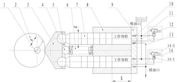
[0018] Such as figure 1 as shown,

[0019] The cam 2 rotates continuously around the rotating shaft 1, the center of the rotating shaft 1 coincides with the center of the base circle of the cam, and the rotational angular velocity is ω. The profile of the cam 2 is a cosine curve shape, which satisfies the following geometric relationship:

[0020] Let the radius of the base circle of the cam be r, the lift of the cam be s, the lift is equal to the movement stroke s of the plunger, t is time, and the cosine contour curve equation of the cam expressed in polar coordinates with the center of the base circle as the origin is:

[0021] (1)

[0022] Since the slider is in direct contact with the cam, this equation is also the displacement equation of the plunger.

[0023] Derivation of formula (1) can get the plunger motion v...


PUM


Abstract

The invention discloses a sinusoidal flow generating device, which comprises a sliding block. The sliding block is connected with a cam, the other side of the sliding block is connected with the top ends of a plurality of plungers, the rod parts of the plungers are arranged in plunger holes in a cylinder, an elastic device is arranged between the sliding block and the cylinder, and the plungers can reciprocate in the plunger holes in the cylinder. The contour shape of the cam meets the following curve equation: Rho=r+s/2(1-cos(Omega t), wherein r is the radius of the base circle of the cam, s is the lift of the cam, and Omega is the rotating angular speed. An electromagnetic one-way valve is arranged in a working cavity formed between each plunger and each plunger hole of the cylinder, the oil inlet of the electromagnetic one-way valve is connected with the working cavity, and the oil outlet of the electromagnetic one-way valve is connected with an oil feeding channel of the flow generating device to control the number of the plungers engaged in flow output simultaneously and to realize the adjustment and the control of the amplitude of sinusoidal flow. The defect that only approximate sinusoidal flow signals can be obtained when a crank-connecting rod mechanism or an eccentric wheel mechanism is adopted to drive the plungers to move is overcome, and standard sinusoidal flow signals can be provided for testing the performance of mechanical parts needing sinusoidal flow as an input signal.

Description

technical field [0001] The invention relates to a flow generating device, the output flow of which is in a (one-way) sinusoidal periodic change. Background technique [0002] The flow output devices used in the project are mainly hydraulic pumps. Hydraulic pumps are divided into two categories: quantitative pumps and variable pumps. It is required that the pulsation of the output flow should be as small as possible. Output a flow signal that changes according to a sine (cosine) curve. For example, in the detection of the damping curve of automobile and motorcycle shock absorbers, the sine flow signal is required as the input signal for performance testing. In order to obtain the flow that changes according to the sinusoidal curve, the following two methods can be used at present: one is to use the flow servo valve in the flow output system of the quantitative pump to control and adjust the flow, and obtain the output flow that changes according to the law of the sinusoidal c...

Claims


Application Information

Patent Timeline
Patent Type & Authority Applications(China)
IPC IPC(8): F04B1/12F04B1/26
Inventor 唐全波
Owner CHONGQING TECH & BUSINESS UNIV
Why Eureka
Try Eureka