Energy-saving system using heat recovery type water source heat pump unit and control method for energy-saving system

A water source heat pump unit, heat recovery technology, applied in heat recovery systems, energy recovery systems for ventilation and heating, and machine operation modes, etc. Quantity waste etc.

Inactive Publication Date: 2012-04-25
安徽日源环保能源科技有限公司
View PDF6 Cites 15 Cited by
  • Summary
  • Abstract
  • Description
  • Claims
  • Application Information

AI Technical Summary

Problems solved by technology

[0003] The existing ground source heat pump system is generally equipped with two sets of heat pump units, one is dedicated to air conditioning, and the other is dedicated to hot water. Usually, the two systems are completely independent. With some improved designs, the hot water unit While another set of heat pump unit is used for cooling, the cooling water on the ground source side is used as the cold source to prepare domestic hot water. In winter, the ground source side is used as the cold source to prepare domestic hot water. However, there are three problems in this system: one is the hot water unit Not participating in the cooling and heating work throughout the year is obviously wasteful in terms of system configuration and the number of buried pipes; both, this system is only applicable to the case where the ground source side is a closed system, and direct groundwater, direct lake water, etc. The situation cannot be applied, or a major improvement is required
Third, the cooling water of the system is used as the heat source of the evaporator of the hot water unit in the cooling season. This temperature is significantly higher than the working temperature of the evaporator of the water source heat pump unit of most equipment manufacturers, and the safety and universality of the system are greatly reduced.

Method used


Image

  • Energy-saving system using heat recovery type water source heat pump unit and control method for energy-saving system
  • Energy-saving system using heat recovery type water source heat pump unit and control method for energy-saving system
  • Energy-saving system using heat recovery type water source heat pump unit and control method for energy-saving system

Examples


Embodiment Construction

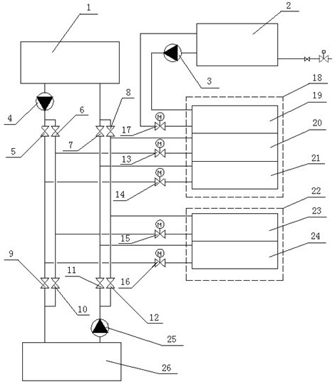
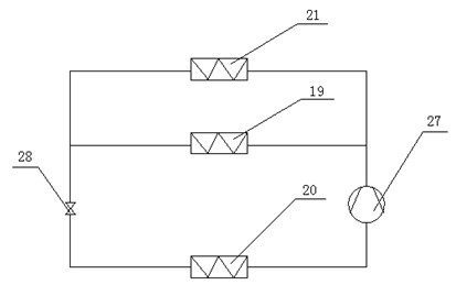
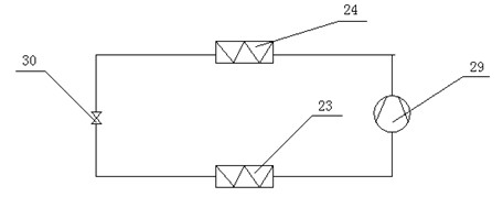
[0032] See figure 1 , an energy-saving system and control method using a heat recovery water source heat pump unit, including a domestic hot water tank 2, an air conditioner terminal 1, a ground source heat exchange system 27, a heat recovery type water source heat pump unit 18 and a water source heat pump unit 22; see figure 2, the heat recovery type water source heat pump unit 18 includes a first compressor 27, a first condenser 21, a first throttling device 28, a first evaporator 20 and a heat recovery heat exchanger 19, the first compressor 27, the first condenser 21, the first throttling device 28, and the first evaporator 20 are cyclically connected, and the first compressor 27, the heat recovery heat exchanger 19, the first throttling device 28, and the first evaporator 20 are cyclically connected; see image 3 , the water source heat pump unit includes a second compressor 29, a second condenser 24, a second throttling device 30 and a second evaporator 23 connected in ...


PUM


Abstract

The invention discloses an energy-saving system using a heat recovery type water source heat pump unit and a control method for the energy-saving system. The energy-saving system using the heat recovery type water source heat pump unit consists of a domestic hot water tank, an air-conditioning tail end, a ground source heat exchange system, the heat recovery type water source heat pump unit and a water source heat pump unit. The energy-saving system can meet the requirements of cold supply, heat supply and hot water supply of a building; in summer, the system can be used for refrigeration and can recover waste heat to prepare domestic hot water during refrigeration; in winter, the unit can supply heat, and the domestic hot water can be prepared; in spring and autumn, the domestic hot water can be prepared at random; and the installed capacity of equipment can be saved to the maximum extent, and the system is energy-saving and environment-friendly and is widely applied to places such as hotels, public houses, hospitals, residences and the like.

Description

[0001] technical field [0002] The invention relates to the field of ground source heat pump systems, in particular to an energy-saving system utilizing a heat recovery type water source heat pump unit and a control method thereof. Background technique [0003] The existing ground source heat pump system is generally equipped with two sets of heat pump units, one is dedicated to air conditioning, and the other is dedicated to hot water. Usually, the two systems are completely independent. With some improved designs, the hot water unit While another set of heat pump unit is used for cooling, the cooling water on the ground source side is used as the cold source to prepare domestic hot water. In winter, the ground source side is used as the cold source to prepare domestic hot water. However, there are three problems in this system: one is the hot water unit Not participating in the cooling and heating work throughout the year is obviously wasteful in terms of system configura...

Claims


Application Information

Patent Timeline
Patent Type & Authority Applications(China)
IPC IPC(8): F25B29/00F25B41/04F25B49/02F24F5/00F24F12/00
CPCY02B30/52Y02B30/563Y02B30/56
Inventor 张明军蒋海洋
Owner 安徽日源环保能源科技有限公司
Why Eureka
Try Eureka