Optical projection tomography motion artifact correction method

An optical projection tomography and motion artifact technology, applied in the field of medical image processing, can solve the problems of needing estimation, inapplicability, and difficulty in identification, etc.

Inactive Publication Date: 2012-04-25
XIDIAN UNIV
View PDF3 Cites 13 Cited by
  • Summary
  • Abstract
  • Description
  • Claims
  • Application Information

AI Technical Summary

Problems solved by technology

The disadvantage of this method is that it is necessary to estimate the trajectory of the

Method used


Image

  • Optical projection tomography motion artifact correction method
  • Optical projection tomography motion artifact correction method
  • Optical projection tomography motion artifact correction method

Examples


Embodiment Construction

[0036] The present invention will be described in further detail below in conjunction with the accompanying drawings.

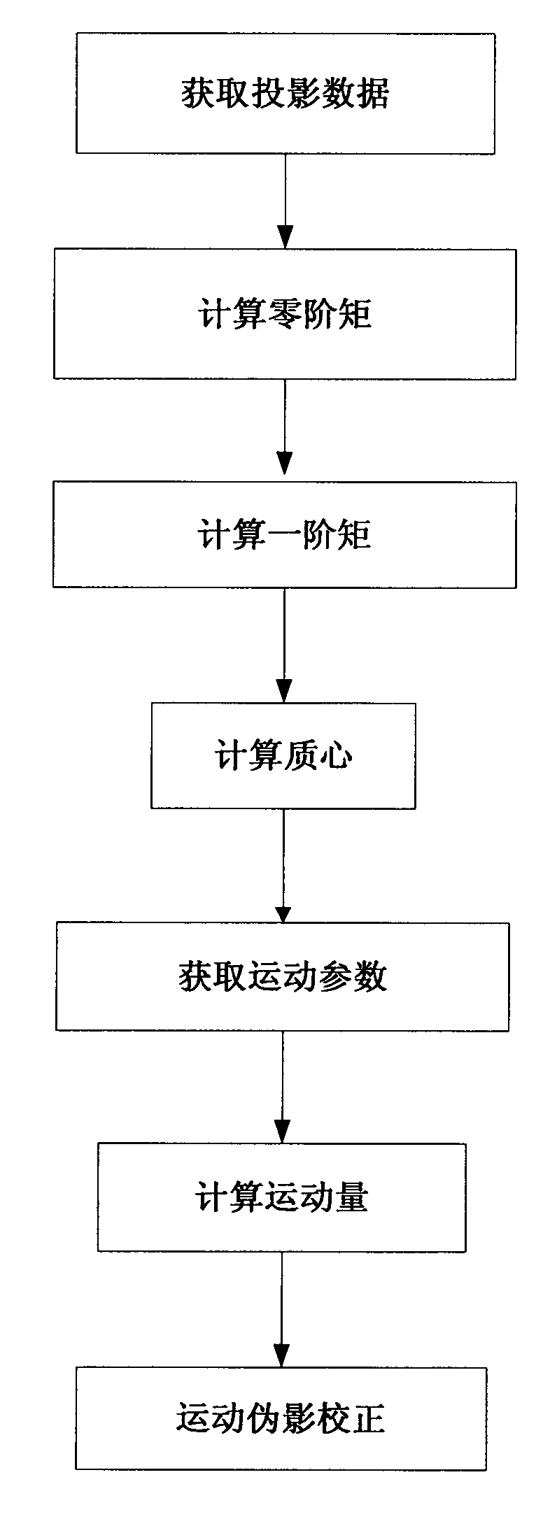
[0037] combined with figure 1 The steps of the present invention are further described.

[0038] Step 1, get projection data:

[0039] First, the irradiation source performs horizontal projection tomography on the sample fixed on the electronically controlled rotary table. The irradiation source uses a laser, and a telecentric lens is used to expand the beam of light into parallel light to illuminate the sample.

[0040] Then, use the detector to acquire projection data of the sample. The collection method of the present invention is as follows: collect one projection data every time the sample is rotated by one angle, and record the projection data collected each time in the computer.

[0041] Step 2, the computer calculates the zero-order distance of the projection data in the following formula:

[0042] C 0 ...


PUM


Abstract

The invention discloses an optical projection tomography motion artifact correction method, using a method for estimating sample motion trail without the basis of feature points. The method comprises the following implementation steps of: (1) obtaining projection data; (2) calculating the zeroth moment of the projection data; (3) calculating the first moment of the projection data; (4) calculating center of mass of the projection data; (5) obtaining a motion parameter; (6) calculating quantity of motion; (7) executing motion artifact correction. In the method, a corresponding relation betweena sample and the projection data is built based on a data consistency condition, motion of the scanned sample is estimated by polynomial, thus, the motion information of the sample is estimated directly from the projection data. The method can be used for projection tomographic reconstruction of the sample, and can improve spatial resolution of an optical tomography system and reduce image artifacts.

Description

technical field [0001] The invention belongs to the field of medical image processing, and further relates to a method for correcting motion artifacts of an optical projection tomography system. The method can be used for image processing of optical projection tomography. Background technique [0002] Optical projection tomography (hereinafter referred to as OPT) is a new type of optical molecular imaging technology, and its imaging principle is similar to that of X-ray computed tomography. OPT can obtain scanning sample structure images, and can use fluorescent dyes or fluorescent proteins for molecular specific labeling to realize molecular characteristic imaging, and the equipment is low in cost and easy to use. During OPT scanning, the movement of the scanned sample and the mechanical instability of the OPT system can cause motion artifacts in the reconstructed image. Motion artifacts can degrade the spatial resolution of the system, produce image artifacts, and even m...

Claims


Application Information

Patent Timeline
IPC IPC(8): G06T5/00G06T7/20
Inventor 朱守平陈冬梅梁继民陈多芳屈晓超赵恒李军陈雪利侯彦宾田捷
Owner XIDIAN UNIV
Why Eureka
Try Eureka