Moulding sand cooling dedusting tower as well as casting moulding sand processing device and method

A technology for dust removal towers and molding sand, which is applied in foundry molding equipment, machinery for cleaning/processing mold materials, and manufacturing tools, etc. The effect of reducing labor intensity, high work efficiency and high-quality treatment

Active Publication Date: 2012-05-02
XINJIANG UYGUR AUTONOMOUS REGION NO 3 MACHINE TOOL WORKS
View PDF4 Cites 17 Cited by
  • Summary
  • Abstract
  • Description
  • Claims
  • Application Information

AI Technical Summary

Problems solved by technology

[0003] The present invention provides a molding sand cooling and dedusting tower, a casting molding sand processing device and a casting molding sand processing method, which overcomes the above-mentioned deficiencies in the prior art, and can effectively solve the existing problems. The foundry sand treatment device has the problems of single function, low efficiency, large space occupation, large sand and dust pollution to the environment

Method used


Image

  • Moulding sand cooling dedusting tower as well as casting moulding sand processing device and method
  • Moulding sand cooling dedusting tower as well as casting moulding sand processing device and method
  • Moulding sand cooling dedusting tower as well as casting moulding sand processing device and method

Examples


Embodiment 1

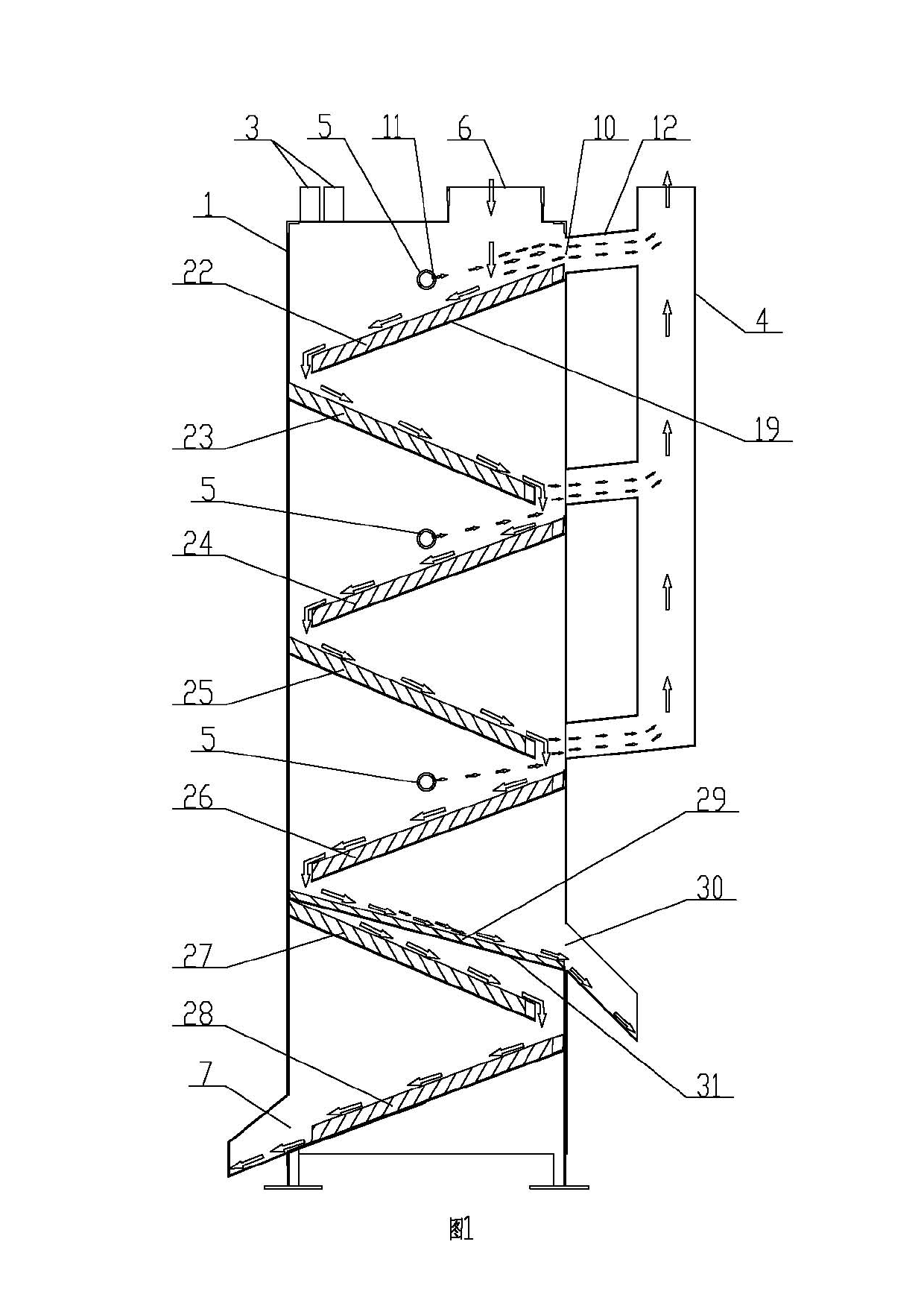
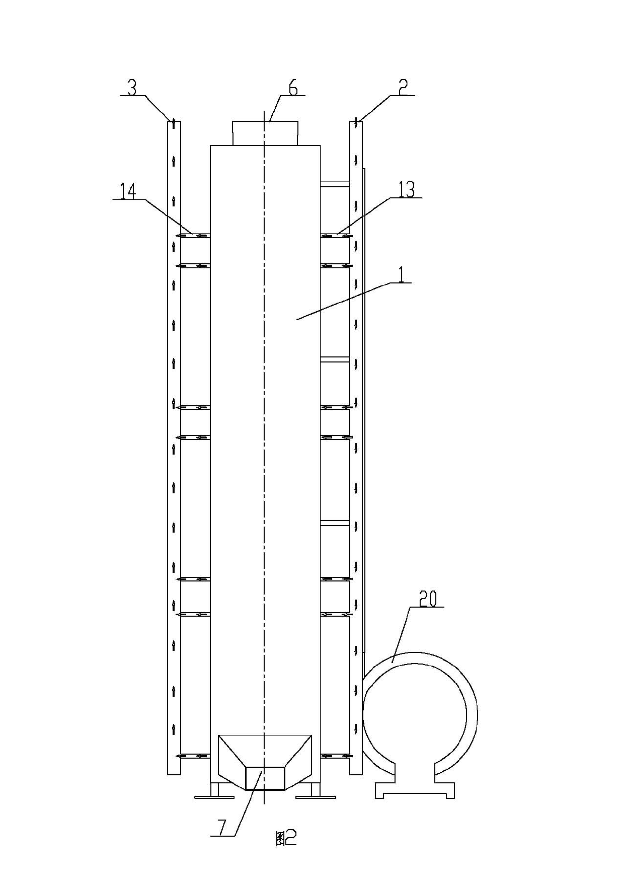
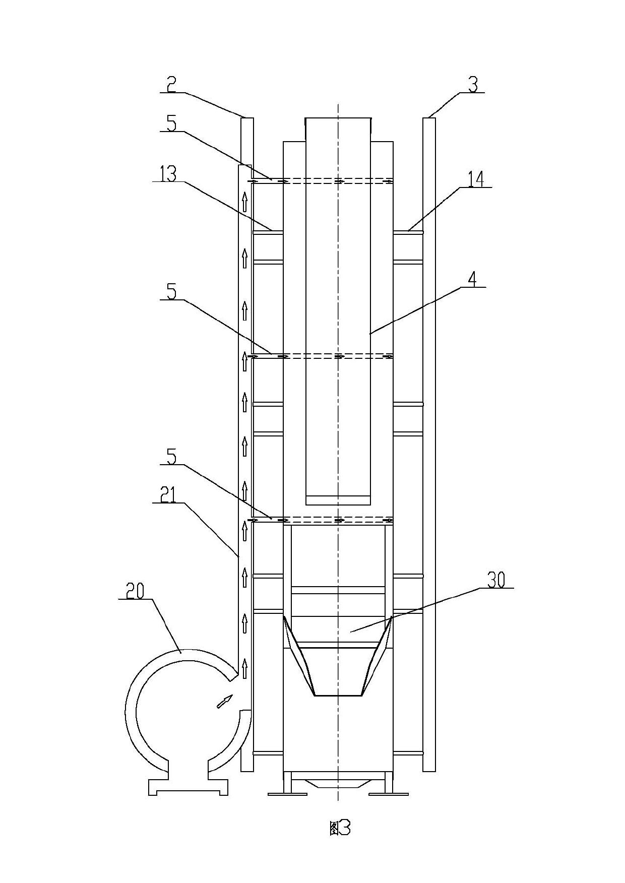
[0035] Embodiment 1: as attached figure 1 , 2 As shown, the molding sand cooling and dedusting tower includes a vertical box 1, a cooling box, an inlet pipe 2, an outlet pipe 3, a dust removal pipe 4 and an air duct 5; the upper end of the vertical box 1 has a sand inlet 6, and the vertical box The inner cavity of the body 1 is fixed with a cooling box whose upper surface is an inclined surface. The upper end of the cooling box is the molding sand inflow end and communicates with the sand inlet 6. The lower end of the cooling box is the molding sand outflow end, corresponding to the vertical cooling box at the lower end. There is a sand outlet 7 on the outside of the box body 1 and it is connected with the outflow end of the molding sand; the water inlet pipe 2 and the water outlet pipe 3 are fixed on the vertical box body 1, the water inlet 8 and the water outlet 9 are on the cooling box, and the water inlet of the cooling box 8 is connected with the water inlet pipe 2, ...

Embodiment 2

[0041] Embodiment 2: as attached Figure 6 , 7 , 9, the foundry sand processing device includes a frame 32, a sand storage tank 33, a longitudinal belt conveyor 34, a transverse belt conveyor 35, a sand collection bucket 36, a magnetic separation conveyor 37, a first sand storage bin 38, a first Bucket elevator 39, first molding sand cooling and dust removal tower 40, second sand storage bin 41, second bucket elevator 42, second molding sand cooling and dust removal tower 43, third sand storage bin 44, third bucket elevator 45, parallel Belt conveyor 46 and sand warehouse 47; sand storage tank 33 is fixedly installed on the left part of frame 32, and filter screen 48 is fixedly installed on the frame 32 above sand storage tank 33, and the lower end of sand storage tank 33 has sand falling port 49. There is a longitudinal belt conveyor 34 below the sand falling port 49. A longitudinal belt 50 capable of transporting materials to the rear is installed on the longitudinal bel...

Embodiment 3

[0045] Embodiment 3: a kind of foundry sand processing method, comprises the following steps:

[0046] (1) The molding sand is coarsely screened by the filter screen 48 , and the larger plastics, larger iron particles and other debris in the molding sand are left above the filter screen 48 , and the separated molding sand falls from the shakeout port 49 ;

[0047] (2) The roughly screened molding sand falls from the shakeout port 49 and moves backward with the longitudinal belt 50 of the longitudinal belt conveyor 34. When it reaches the front of the longitudinal belt sand cutting baffle 52, the longitudinal belt sand cutting baffle 52 pushes the molding sand It falls onto the transverse belt 51 of the transverse belt conveyor 35, and the transverse belt 51 moves to the right to send the molding sand into the sand collection bucket 36, and the sand collection bucket 36 falls into the magnetic separation conveyor 37 for magnetic separation, and the fine iron in the molding...


PUM


Abstract

The invention relates to the technology field of processing and recycling of casting moulding sand and in particular relates to a moulding sand cooling dedusting tower as well as a casting moulding sand processing device and a using method thereof. The moulding sand cooling dedusting tower comprises a vertical box body, a cooling box, a water inlet pipe, a water outlet pipe, a dedusting pipe and an air pipe, wherein a sand inlet is arranged at the upper end of the vertical box body; the cooling box of which the upper surface is an oblique surface is fixed in the inner cavity of the vertical box body; the upper end of the cooling box is a moulding sand flow-in end and communicated with the sand inlet; the lower end of the cooling box is a moulding sand flow-out end; and a sand outlet is arranged at the exterior of the vertical box body at the lower end of the corresponding cooling box and communicated with the moulding sand flow-out end. The device provided by the invention has a reasonable and compact structure, relatively large plastic and iron particles are separated through a filtering block net, small iron impurities are separated by a magnetic separation conveyor, and fine screening and cooling dedusting of the moulding sand are realized through the moulding sand cooling dedusting tower, therefore, the moulding sand cooling dedusting tower can be used for processing the casting moulding sand in an energy-saving, efficient and high-quality mode, has high working efficiency, is economical and environmentally-friendly, and can be used for reducing the labor intensity, the potential safety hazard and the labor cost.

Description

technical field [0001] The invention relates to the technical field of casting molding sand treatment and reuse, and relates to a molding sand cooling and dedusting tower, a casting molding sand processing device and a casting molding sand processing method. Background technique [0002] The processing of foundry sand generally includes cooling, dust removal and screening. Currently, the existing processing devices for foundry sand have relatively single functions and low efficiency. Generally, one processing device can only complete one of the processing processes, and The existing casting sand treatment device occupies a relatively large site, and the site blows sand and dust during work is relatively large, which will cause certain pollution to the environment. Contents of the invention [0003] The present invention provides a mold sand cooling and dedusting tower, a casting mold sand treatment device and a casting mold sand treatment method, which overcomes the above-...

Claims


Application Information

Patent Timeline
IPC IPC(8): B22C5/08B22C5/00
Inventor 高长乐于胜存罗仁全杨立春赵英杰张学明马述俭李勇强
Owner XINJIANG UYGUR AUTONOMOUS REGION NO 3 MACHINE TOOL WORKS
Why Eureka
Try Eureka