Ultra-deepwater offshore oil-gas engineering developing system and mounting method thereof

A technology of engineering development and installation method, applied in the direction of infrastructure engineering, fluid extraction, earthwork drilling, etc., can solve the problem that the safety, environmental protection, feasibility and economical applicability of engineering equipment and engineering models cannot meet the requirements, construction cost , high operating costs and maintenance costs, no effective technology to prevent typhoons and hurricanes, etc., to shorten the installation period, reduce investment costs, and reduce production costs

Active Publication Date: 2012-05-02
DALIAN UNIV OF TECH
View PDF6 Cites 37 Cited by
  • Summary
  • Abstract
  • Description
  • Claims
  • Application Information

AI Technical Summary

Problems solved by technology

[0006] Based on the above problems, the current limited working water depth of TLP platform is about 1500m, and the limited working water depth of semi-submersible platform is about 3000m, and the construction cost, operation cost and maintenance cost of these traditional surface production devices applied in deep sea are high
[0007] In addition, traditional offshore oil and gas field development operations can only be carried out after all facilities are in place, which seriously delays the operation period and reduces the efficiency of production operations, thereby increasing the cos

Method used


Image

  • Ultra-deepwater offshore oil-gas engineering developing system and mounting method thereof
  • Ultra-deepwater offshore oil-gas engineering developing system and mounting method thereof
  • Ultra-deepwater offshore oil-gas engineering developing system and mounting method thereof

Examples


Embodiment Construction

[0044] The present invention will be further described below in conjunction with the accompanying drawings.

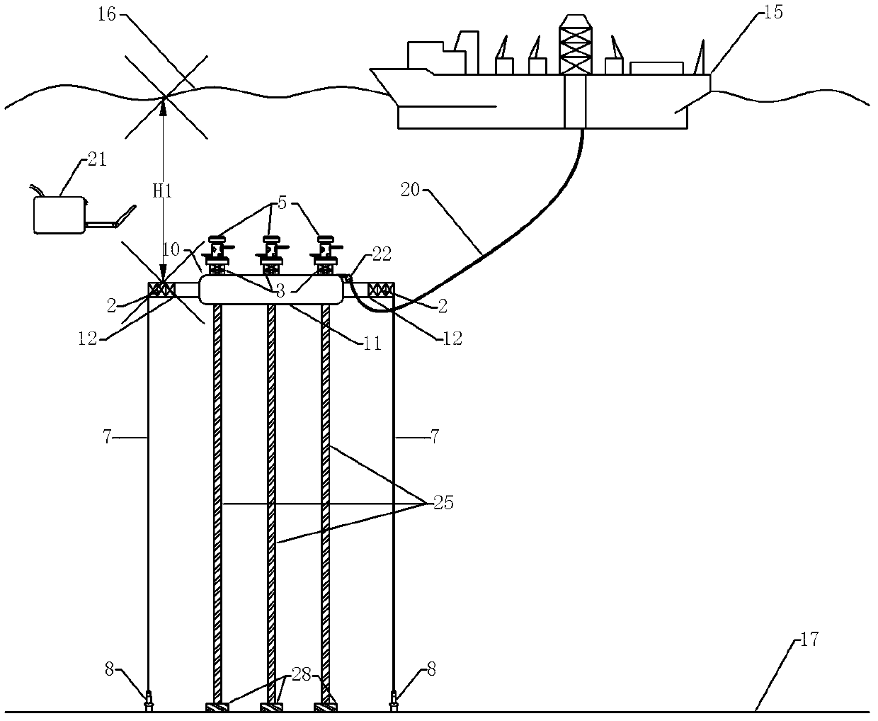
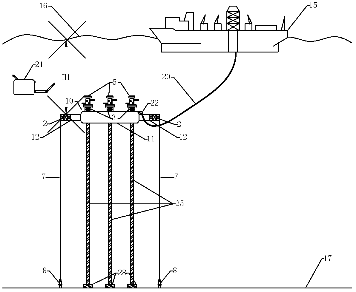
[0045] like figure 1 As shown, an ultra-deep water offshore oil and gas engineering development system mainly includes surface floating production device 15, riser support buoy 10, tension mooring device, upper flexible jumper 20, lower rigid riser 25, oil production equipment 5 and seabed Wellhead 28.

[0046] The oil recovery equipment 5 is installed on the riser support buoy 10 .

[0047] The riser support buoy 10 is located at H1 under the water surface 16 to avoid the turbulent flow area under the sea surface, so that the riser support buoy 10 is hardly affected by the wind, waves and currents near the sea surface, and maintains a good position. performance.

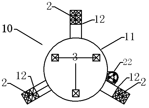
[0048] like Figure 1-2 As shown, the riser support buoy 10 adopts a combined structure of a central column structure 11 and three rectangular section cantilever buoys 12 connected to the edge of the ce...


PUM


Abstract

The invention discloses an ultra-deepwater offshore oil-gas engineering developing system and a mounting method thereof. The ultra-deepwater offshore oil-gas engineering developing system comprises a water-surface floating production device, a stand pipe supporting pontoon, an underwater oil extraction device, an upper part flexible jumper pipe, a lower part rigid stand pipe and a seabed well mouth device; the underwater oil extraction device is arranged on the stand pipe supporting pontoon; and benthonic oil-gas resources finally reach the water-surface floating production device through the seabed well mouth device, the lower part rigid stand pipe, the stand pipe supporting pontoon, the underwater oil extraction device and the upper part flexible jumper pipe. According to the ultra-deepwater offshore oil-gas engineering developing system disclosed by the invention, the huge weights of underwater stand pipes and an oil extraction device are borne by the stand pipe supporting pontoon, and the dynamic load to be borne by the water-surface floating production device is reduced, thus the design requirements on the water-surface floating production device are reduced; in addition, the underwater oil extraction device is arranged on the stand pipe supporting pontoon, thus the ultra-deepwater oil-gas extraction operation can be carried out by the mesopelagic water-surface floating production device and the oil extraction device, the investment cost is rather largely reduced, and the installation and the maintenance are facilitated.

Description

technical field [0001] The invention relates to an offshore oil and gas development technology, in particular to an ultra-deep water offshore oil and gas engineering development system and an installation method thereof. Background technique [0002] With the gradual depletion of oil and gas resources in land, offshore and middle-deep sea areas, in order to meet the huge demand of human beings for oil resources, the development of deep sea (500-1500m) and ultra-deep sea (above 1500m) oil and gas fields is the main growth point of the world oil industry. [0003] At present, the typical deepwater offshore oil and gas engineering development model in the world is "surface production device + riser system + subsea production system", in which the surface production device includes a floating structure and an upper oil and gas processing system. As the only structure connecting the surface part and the subsea production system, the riser system is an important part of offshore o...

Claims


Application Information

Patent Timeline
IPC IPC(8): E21B43/01E21B43/017E21B43/013
CPCE21B17/015
Inventor 黄一甄兴伟张崎刘刚李红霞
Owner DALIAN UNIV OF TECH
Why Eureka
Try Eureka