Automatic exhaust cooling system

A cooling system and automatic exhaust technology, which is applied in the direction of engine cooling, liquid cooling, coolant flow control, etc., can solve the problem that air bubbles are not easy to discharge, and achieve the effect of ensuring heat dissipation efficiency

Inactive Publication Date: 2012-05-02
冯俊
View PDF5 Cites 11 Cited by
  • Summary
  • Abstract
  • Description
  • Claims
  • Application Information

AI Technical Summary

Problems solved by technology

However, the air bubbles in the cooling system are not easy to discharge, so it is necessary to specially design the exhaust valve on the thermostat

Method used


Image

  • Automatic exhaust cooling system
  • Automatic exhaust cooling system
  • Automatic exhaust cooling system

Examples


Embodiment 1

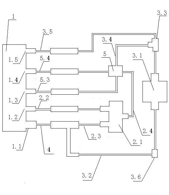
[0024] An automatic exhaust cooling system includes a large circulation pipeline connected to an engine water jacket 1, a small circulation pipeline and an expansion tank 5.

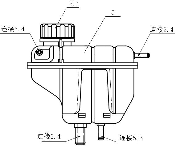
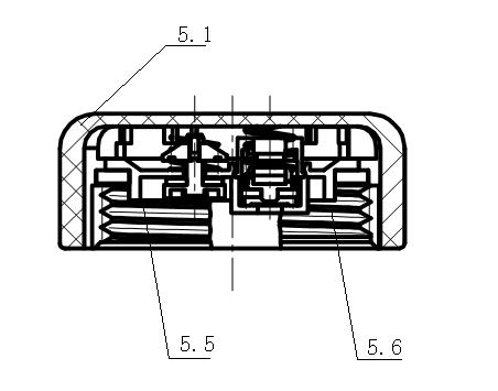
[0025] People's Communications Publishing House 2001.5 "Automobile Engineering Handbook-Design" page 182 discloses a general layout of an automobile cooling system. In this embodiment, the large circulation pipeline, the small circulation pipeline and the expansion tank 5 connected to the engine water jacket 1 can adopt the components and their connection methods disclosed in the above manual. In particular, in this embodiment, the expansion water tank 5 is preferably the pressurized auxiliary water tank disclosed on page 189 of the manual, and the thermostat may not have an exhaust valve.

[0026] Because the engine layout of the mini-car is mid-mounted, and in order to ensure the minimum ground clearance of the vehicle, the engine of the mini-car is tilted at a certain angle, causing the thermostat to ...

Embodiment 2

[0031] An automatic exhaust cooling system includes a large circulation pipeline connected to an engine water jacket 1, a small circulation pipeline and an expansion tank 5. When the engine temperature is lower than 85°C, the circulating water in the engine water jacket 1 directly enters the small circulation pipe through the adjustment of the thermostat installed on the water jacket water outlet 1.1 or the water jacket water inlet 1.2 of the engine water jacket 1 Road; when the engine temperature is higher than 85°C, through the regulation of the thermostat, the circulating water directly enters the large circulation pipeline and the small circulation pipeline.

[0032] Further, the water jacket water outlet 1.1 of the engine water jacket 1 is connected to the return water pipe 3.5 through the water outlet pipe 4 in one way, and connected to the radiator water inlet pipe 2.3 in the other way. The small circulation pipeline includes a heater 3.1 whose water inlet is connected ...


PUM


Abstract

The invention provides a cooling system for a vehicle, with functions of automatically exhausting gas in a cooling loop and replenishing water. The cooling system comprises a large circulating pipeline, a small circulating pipeline and an expansion water tank that are connected with an engine water jacket, wherein the engine water jacket is provided with a water replenishing hole and an exhaust hole, the water replenishing hole is communicated with the expansion water tank through a water replenishing pipe, and the exhaust hole is communicated with the expansion water tank through an exhaust pipe. By adopting the technical scheme provided by the invention, blockage due to dead regions of parts, gasification of a cooling liquid at high temperature, and gas brought in by expelling high-pressure gas outside the cylinder gasket or injecting the cooling liquid of the engine cooling system can be effectively eliminated, thus heat radiating efficiency of the engine cooling system is ensured. Meanwhile, the expansion water tank of the cooling system has a water replenishing function, loss of the cooling liquid can be immediately made up, and reliability of a cooling and heat-radiating system is improved.

Description

technical field [0001] The invention relates to a device for cooling a cylinder or a cylinder head with a liquid, in particular to a vehicle cooling system with the functions of automatically discharging gas in a cooling circuit and replenishing water in time. Background technique [0002] The cooling system of the automobile engine is a forced circulation water cooling system, that is, the water pump is used to increase the pressure of the coolant, and the coolant is forced to circulate in the engine to take away excess heat. The cooling system is mainly composed of pipelines, water pumps, radiators, heaters, expansion tanks, thermostats, engine blocks, water jackets in cylinder heads, and accessories. Usually, in the cooling system, there are two heat dissipation cycles: one is the "small cycle", that is, after the car is cold, the engine is gradually warming up, and the thermostat is closed. At this time, the coolant passes through the heater to make the engine Reach the...

Claims


Application Information

Patent Timeline
Patent Type & Authority Applications(China)
IPC IPC(8): F01P3/20F01P11/00F01P11/02F01P7/16
Inventor 冯俊陈亚华杨小放
Owner 冯俊
Why Eureka
Try Eureka