
Planar directional pattern reconfigurable method and antenna with six-wave-beam selectivity

A selective, planar technology, applied in the direction of antenna, antenna grounding device, radiating element structure, etc., can solve the problem of not using switch and control circuit, etc., to improve practical applicability, strong practicability and operability, simple structure

Inactive Publication Date: 2012-05-02
TIANJIN UNIV
View PDF4 Cites 33 Cited by
  • Summary
  • Abstract
  • Description
  • Claims
  • Application Information

AI Technical Summary

Problems solved by technology

Although this antenna can achieve more sub-pattern reconstructions, the maximum direction of the antenna's pitch angle pattern is 45 degrees, which is not in the horizontal plane
In addition, the antenna uses the presence or absence of copper sheets to replace the on-off of the switch, and does not use the actual switch and control circuit

Method used


Image

  • Planar directional pattern reconfigurable method and antenna with six-wave-beam selectivity
  • Planar directional pattern reconfigurable method and antenna with six-wave-beam selectivity
  • Planar directional pattern reconfigurable method and antenna with six-wave-beam selectivity

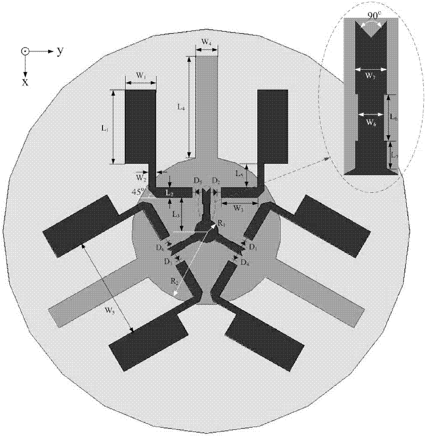
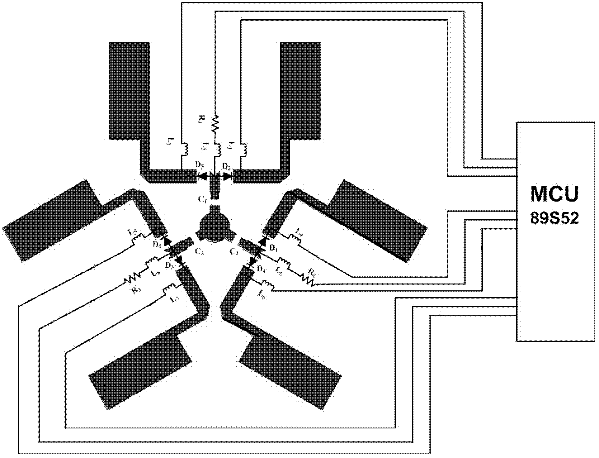
Examples


Embodiment Construction

[0024] The antenna design mentioned in the present invention is based on a planar symmetric structure. The antenna is mainly composed of the radiation unit layer and the ground plane layer. The feed of the antenna adopts back feed.

[0025] The radiating element layer of the antenna is composed of an active circular patch located in the center and a rectangular parasitic patch surrounding it. The antenna chooses a rectangular patch as the main radiation unit, which greatly simplifies the structure of the antenna. The rectangular radiating patch is connected to the central circular unit of the antenna through a strip line and a microstrip line, and a radio frequency PIN diode is inserted into the microstrip line. By controlling the on-off state of the diode, the surrounding rectangular radiation patch can selectively radiate outward. The ground plane of the antenna adopts partial grounding technology. The grounding plate is formed by connecting the central circular patch and t...


PUM


Abstract

The invention relates to antennas in wireless communication, and provides an antenna which can carry out pattern reconfigurability for more directions and has stronger practicability. The technical scheme in the invention is as follows: the planar directional pattern reconfigurable antenna with six-wave-beam selectivity consists of an antenna substrate, a radiation unit layer and a grounding plate layer, wherein the radiation unit layer consists of a circular active patch positioned at the center of the radiation unit layer and rectangular parasitic patches arranged around the radiation unit layer, and the rectangular parasitic patches are connected with a circular unit at the center of the antenna through strip lines and micro-strip lines; a radio frequency PIN diode is inserted into each micro-strip line; the circumferential rectangular parasitic patches selectively radiate outwards by controlling the on-off status of the diode; the grounding plate layer of the antenna adopts a partial grounding mode and is formed by connecting the center circular patch with the rectangular patches at equal angle-intervals; and the antenna substrate is in a circular disk shape and is made from apolytetrafluoroethylene (PTFE) material. The technical scheme is mainly applied to design and manufacture of the antenna.

Description

Technical field [0001] The present invention relates to an antenna in wireless communication, and in particular to a planar pattern reconfigurable antenna with six beam selectivity. Background technique [0002] With the rapid development of wireless communication technology, antennas with multiple characteristics have attracted a lot of attention. As a new type of antenna, reconfigurable antenna has become a research focus in recent years. The reconfigurable antenna can realize the function of multiple antennas on one antenna, thereby realizing multiple diversity modes. As an important aspect in the research of reconfigurable antennas, pattern reconfigurable antennas can achieve selective switching of the pattern through switch control, thereby realizing the effective use of space resources in a variety of environments. The reconfigurable pattern antenna can better improve the system gain, improve communication security, and avoid noise interference. At the same time, directi...

Claims


Application Information

Patent Timeline
Patent Type & Authority Applications(China)
IPC IPC(8): H01Q1/38H01Q1/48H01Q3/01
Inventor 蔡晓涛王安国马宁冷文
Owner TIANJIN UNIV
Learn More