Power flow control system
A power flow control and controller technology, applied in AC network circuits and AC networks to reduce harmonics/ripples, climate change adaptation, etc. Phase unbalance, increased flexibility, overall cost reduction effect
- Summary
- Abstract
- Description
- Claims
- Application Information
AI Technical Summary
Problems solved by technology
Method used
Image

Examples
Embodiment Construction
[0028] Embodiments of the present invention will be further described below in conjunction with the accompanying drawings.
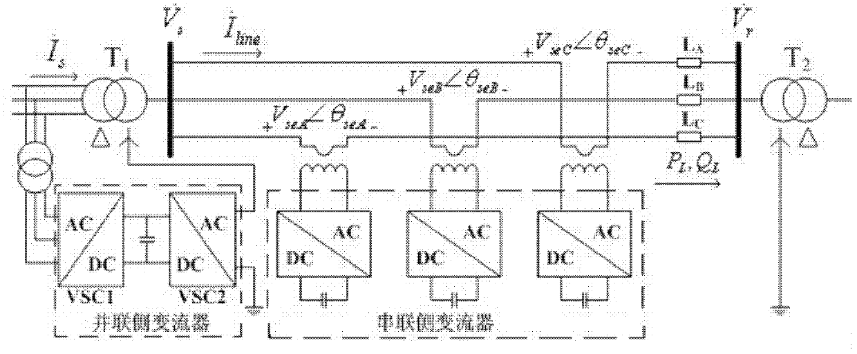
[0029] see figure 1 , a power flow control system, including a parallel-side converter, a series-side converter, a first Y-Δ transformer T1, a second Y-Δ transformer T2, the parallel-side converter is located between the grid and the first Y-Δ transformer Between T1, the series-side converter is located between the first Y-Δ transformer T1 and the second Y-Δ transformer T2; the parallel-side converter includes a back-to-back three-phase converter VSC1 and a single-phase converter The three-phase converter VSC2 is formed by DC capacitor coupling. The three-phase converter VSC1 is connected to the transmission line between the grid and the first Y-Δ transformer T1 through a transformer. The single-phase converter VSC2 converts the fundamental wave in the grid into The third harmonic, and through the neutral point of the Y-shaped winding of the first Y-Δ t...
PUM
 Abstract
Description
Claims
Application Information
 - Generate Ideas
- Intellectual Property
- Life Sciences
- Materials
- Tech Scout
- Unparalleled Data Quality
- Higher Quality Content
- 60% Fewer Hallucinations
Browse by: Latest US Patents, China's latest patents, Technical Efficacy Thesaurus, Application Domain, Technology Topic, Popular Technical Reports.
© 2025 PatSnap. All rights reserved.Legal|Privacy policy|Modern Slavery Act Transparency Statement|Sitemap|About US| Contact US: help@patsnap.com