
Fiber-transmission-based interface circuit

An interface circuit and optical fiber transmission technology, which is applied in the field of interface circuits, can solve the problems of few types of circuit interface boards, unable to meet the special requirements of the automatic control system of rolling mill thickness, and signal attenuation.

Inactive Publication Date: 2012-05-02
CHINA NON-FERROUS METALS PROCESSING TECH CO LTD
View PDF4 Cites 0 Cited by
  • Summary
  • Abstract
  • Description
  • Claims
  • Application Information

AI Technical Summary

Problems solved by technology

[0002] In the automatic thickness control system of metal plate and strip mills, commonly used external measurement components include linear variable differential transmitter (LVDT), magnetic ruler, magnetic induction position switch, etc. The output signal of external measurement components is often related to the PLC of the control system Or the computer is far away, and the signal attenuation is particularly serious, especially the high-precision signal may seriously affect the measurement accuracy due to too far away. overall performance
At present, there are very few types of circuit interface boards specially used for long-distance transmission produced by domestic and foreign manufacturers, and due to different starting points of design, they cannot meet the special requirements for the automatic control system of rolling mill thickness; The receiving circuit board is very expensive and cannot meet the special needs of the rolling mill thickness automatic control system

Method used


Image

  • Fiber-transmission-based interface circuit
  • Fiber-transmission-based interface circuit
  • Fiber-transmission-based interface circuit

Examples


Embodiment Construction

[0013] The technical solution of the present invention will be described in further detail below through embodiments and in conjunction with the accompanying drawings.

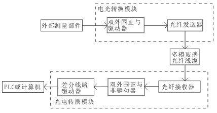
[0014] Such as figure 1 As shown, the present invention is based on an interface circuit for optical fiber transmission, which includes an electro-optic conversion module, a transmission fiber and a photoelectric conversion module. Composed of positive and non-driver and differential line driver, the external measurement component is connected to the input end of the double peripheral positive and driver, the double peripheral positive and driver, optical fiber transmitter, optical fiber receiver, dual peripheral positive and non driver and differential line driver in sequence In series, the optical fiber transmitter and optical fiber receiver are connected through multimode glass optical fiber cables, and the differential line driver is connected to PLC or computer.

[0015] In the rolling mill thickness aut...


PUM


Abstract

The invention discloses a fiber-transmission-based interface circuit, which comprises an electro-optical conversion module, a transmission fiber and a photoelectric conversion module, wherein the electro-optical conversion module consists of a fiber transmitter and dual peripheral positive AND drivers; the photoelectric conversion module consists of a fiber receiver, dual peripheral positive NAND drivers and a differential line driver; external measurement parts are connected with the input ends of the dual peripheral positive AND drivers; the dual peripheral positive AND drivers, the fiber transmitter, the fiber receiver, the dual peripheral positive NAND drivers and the differential line driver are sequentially connected in series; the fiber transmitter is connected with the fiber receiver through a multimode glass optical fiber cable; and the differential line driver is connected with a programmable logic controller (PLC) or a computer. By the fiber-transmission-based interface circuit, the external measurement parts in an automatic rolling mill thickness control system can perform remote signal transmission with the PLC or the computer; and stability, reliability and high measurement accuracy can be achieved.

Description

technical field [0001] The invention relates to an interface circuit, in particular to an interface circuit based on optical fiber transmission, which is used for signal transmission between an external measurement component and a control system in an automatic thickness control system of a rolling mill. Background technique [0002] In the automatic thickness control system of metal plate and strip mills, commonly used external measurement components include linear variable differential transmitter (LVDT), magnetic ruler, magnetic induction position switch, etc. The output signal of external measurement components is often related to the PLC of the control system Or the computer is far away, and the signal attenuation is particularly serious, especially the high-precision signal may seriously affect the measurement accuracy due to too far away. overall performance. At present, there are very few types of circuit interface boards specially used for long-distance transmissio...

Claims


Application Information

Patent Timeline
IPC IPC(8): H04B10/12H04B10/25
Inventor 田刚王宾李江华宏熊克凯
Owner CHINA NON-FERROUS METALS PROCESSING TECH CO LTD
Features
  • Generate Ideas
  • Intellectual Property
  • Life Sciences
  • Materials
  • Tech Scout
  • Unparalleled Data Quality
  • Higher Quality Content
  • 60% Fewer Hallucinations
Learn More