
Signal transfer apparatus of computer

A signal transmission and computer technology, applied in computing, optical fiber transmission, transmission systems, etc., can solve the problems of signal transmission rate limitation, inability to meet data transmission volume and transmission rate growth, etc.

Inactive Publication Date: 2003-12-10
SAMSUNG ELECTRONICS CO LTD
View PDF0 Cites 0 Cited by
  • Summary
  • Abstract
  • Description
  • Claims
  • Application Information

AI Technical Summary

Problems solved by technology

However, since the R-C time constant has a critical value, the signal transmission rate is limited
Therefore, metal wires and cables 15 or 25 cannot meet the demands of increasing data transmission volume and transmission rate.
In addition, when information signals are transmitted through metal wires, it is likely to generate electromagnetic interference (EMI)

Method used


Image

  • Signal transfer apparatus of computer
  • Signal transfer apparatus of computer
  • Signal transfer apparatus of computer

Examples


Embodiment Construction

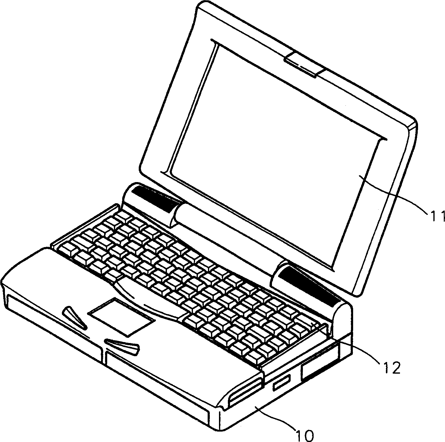
[0020] see Figure 4 The computer signal transmission device of the first embodiment of the present invention includes: a substrate 30 installed on the computer main system frame 100, a driver 31 installed on the substrate 30, a semiconductor laser group 35 driven by the driving signal of the driver 31 , the optical fiber bundle 40 that transmits the light emitted by the semiconductor laser group 35 to the photoreceiver group 45 of the display 110 , and the converter 51 that converts the signal detected by the photoreceiver group 45 into a video signal.

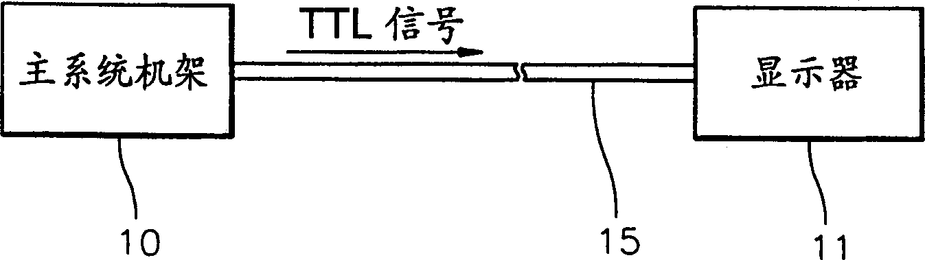
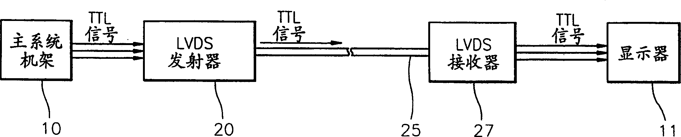
[0021] A graphics card may serve as the substrate 30, in which case the substrate 30 outputs eg 16-bit, 32-bit or 64-bit parallel video signals, ie Transistor-Transistor Logic (TTL) signals.

[0022] The driver 31 individually converts each TTL signal into a current signal. Here, if the TTL signal is at a high level, the driver 31 outputs an ON (conducting) current signal, and if the TTL signal is at a low level, the driver ...


PUM


Abstract

A signal transfer apparatus of a computer, having a substrate installed in a main system frame of the computer, a driving device installed on the substrate for converting a video signal into a current signal, a semiconductor laser array for emitting light corresponding to the current signal from the driving device, an optical fiber bundle for transferring the light emitted from the semiconductor laser array to a display, a photo receiver array for converting the light transferred through the optical fiber bundle into a current signal, and a converter for converting the current signal output from the photo receiver array into a video signal.

Description

technical field [0001] The invention relates to a computer signal transmission device, especially a signal transmission device capable of transmitting information from a main system frame (main system frame) equipped with a computer system to a display at a high transmission rate. Background technique [0002] figure 1 Shown is a conventional portable computer, which includes a main system chassis 10 housing a computer system, a display 11 for displaying various information in the main system chassis 10, and a keyboard 12 for inputting various information and commands. [0003] The display 11 may be a liquid crystal display (LCD) or a plasma display panel (PDP). In recent years, the demand for high-resolution and large displays has increased. Moreover, the amount of data transmitted from the main system rack 10 to the display 11 and the data transmission rate are also increasing. [0004] In this conventional computer, such as figure 2 As shown, a cable 15 made of metal...

Claims


Application Information

Patent Timeline
Patent Type & Authority Patents(China)
IPC IPC(8): G06F3/00G06F1/16G06F3/14G09G5/00H04B10/00H04B10/2507H04B10/2581
CPCG06F3/1431G09G5/006G06F1/16
Inventor 金范洙申铉国高秉天
Owner SAMSUNG ELECTRONICS CO LTD
Features
  • Generate Ideas
  • Intellectual Property
  • Life Sciences
  • Materials
  • Tech Scout
  • Unparalleled Data Quality
  • Higher Quality Content
  • 60% Fewer Hallucinations
Learn More