Communication equipment test device
A technology of testing equipment and communication equipment, applied in transmission monitoring, electrical components, transmission systems, etc., can solve problems such as error-prone, costly, and time-consuming, and achieve the effect of flexible and fast testing
- Summary
- Abstract
- Description
- Claims
- Application Information
AI Technical Summary
Problems solved by technology
Method used
Image
Examples
Embodiment 1
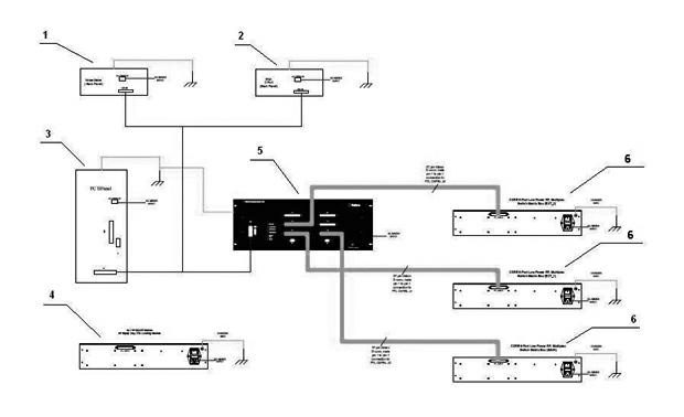
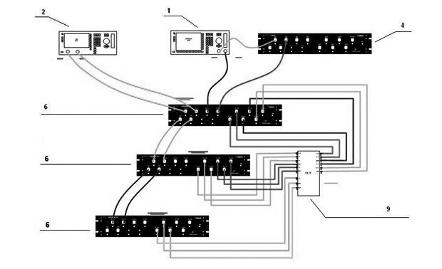
[0040] Embodiment one: see attached figure 1 And attached figure 2 Shown, a multiport low power test of a duplex filter.
[0041] Before the duplex filter is put into use in the communication base station, it is necessary to effectively test its various indicators, and these test indicators include S parameters and so on. S parameters are network parameters based on the relationship between incident waves and reflected waves, which are suitable for microwave circuit analysis. The circuit network is described by the reflected signal of the device port and the signal transmitted from the port to another port. For a two-port network, specifically include S11 (reflection coefficient of port 1 when port 2 is matched), S21 (forward transmission coefficient from port 1 to port 2 when port 2 is matched), S12 (port 2 to port 1 when port 1 is matched Reverse transmission coefficient), S22 (reflection coefficient of port 2 when port 1 is matched). For duplex filters, this is one of the...
Embodiment 2
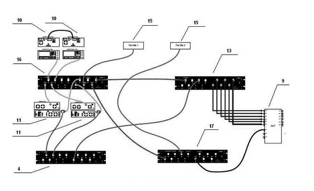
[0046] Embodiment two: see attached image 3 And attached Figure 4 Shown, multi-port high power VSWR test.
[0047] The difference from Embodiment 1 is: (1) Since it is a high-power test, the core module to be tested is selected as the high-power core module 13; (2) DUT 9 has 6 ports to be tested, so only one stage is required High-power core module 13 without expansion; (3) signal source 10 is connected with variable power source module 16, high-power core module 13 is connected with radio frequency power amplifier 11 through variable option module 14, radio frequency power amplifier 11 It is connected with the variable power source module 16 , and the variable power source module 16 is connected with a power meter 15 ; (4) The standing wave ratio tester 17 is connected with the variable power source module 16 .
Embodiment 3
[0048] Embodiment three: see attached Figure 5 And attached Figure 6 As shown, the multiport test.
[0049] The difference from Embodiment 1 and Embodiment 2 is that the 6 ports to be tested of the DUT 9 are connected to the low-power core module 6 , and the other 6 ports to be tested are connected to the high-power core module 13 . The test equipment includes a spectrum analyzer 12 .
PUM
 Abstract
Description
Claims
Application Information
 - R&D
- Intellectual Property
- Life Sciences
- Materials
- Tech Scout
- Unparalleled Data Quality
- Higher Quality Content
- 60% Fewer Hallucinations
Browse by: Latest US Patents, China's latest patents, Technical Efficacy Thesaurus, Application Domain, Technology Topic, Popular Technical Reports.
© 2025 PatSnap. All rights reserved.Legal|Privacy policy|Modern Slavery Act Transparency Statement|Sitemap|About US| Contact US: help@patsnap.com


