
Method for inhibiting grid emission of pulsed travelling wave tube

A technology for suppressing pulses and traveling wave tubes, applied in traveling wave tubes, electronic tubes with speed/density modulation electron flow, etc., can solve problems such as traveling wave tube failure, transmitter ignition failure, modulator ignition, etc., to achieve Guarantee reliability and stability, long service life, eliminate the effect of grid emission

Inactive Publication Date: 2012-05-09
INST OF ELECTRONICS CHINESE ACAD OF SCI
View PDF3 Cites 4 Cited by
  • Summary
  • Abstract
  • Description
  • Claims
  • Application Information

AI Technical Summary

Problems solved by technology

[0003] In the electron gun of the grid-controlled pulse traveling wave tube, the grid is used to play the role of the control electrode. The control electrode itself should not emit electrons. If the control electrode emits electrons, it will disturb the injection of electrons emitted from the cathode. The laminar flow of the traveling wave tube will deteriorate the laminar flow of the electron beam, or cause the modulator to fire. work reliability and stability
At present, molybdenum (Mo) is used as the grid material in grid-controlled pulse traveling wave tubes. This is because molybdenum not only has the characteristics of high-temperature electric vacuum materials, but also has good plastic processing performance. Extreme thermal electron emission phenomenon, causing the transmitter to malfunction and fail
At present, the measure usually taken for this phenomenon is to modify the surface of the molybdenum-based grid, that is, to add a layer of anti-emission film (such as C, Au, Hf, Pt, etc.) To a certain extent, the grid emission phenomenon is improved, but there is a problem of weak bonding between the surface-modified film and the substrate, and there is a phenomenon of shedding, so secondary problems will occur and affect the reliability and stability of the pulse traveling wave tube.

Method used

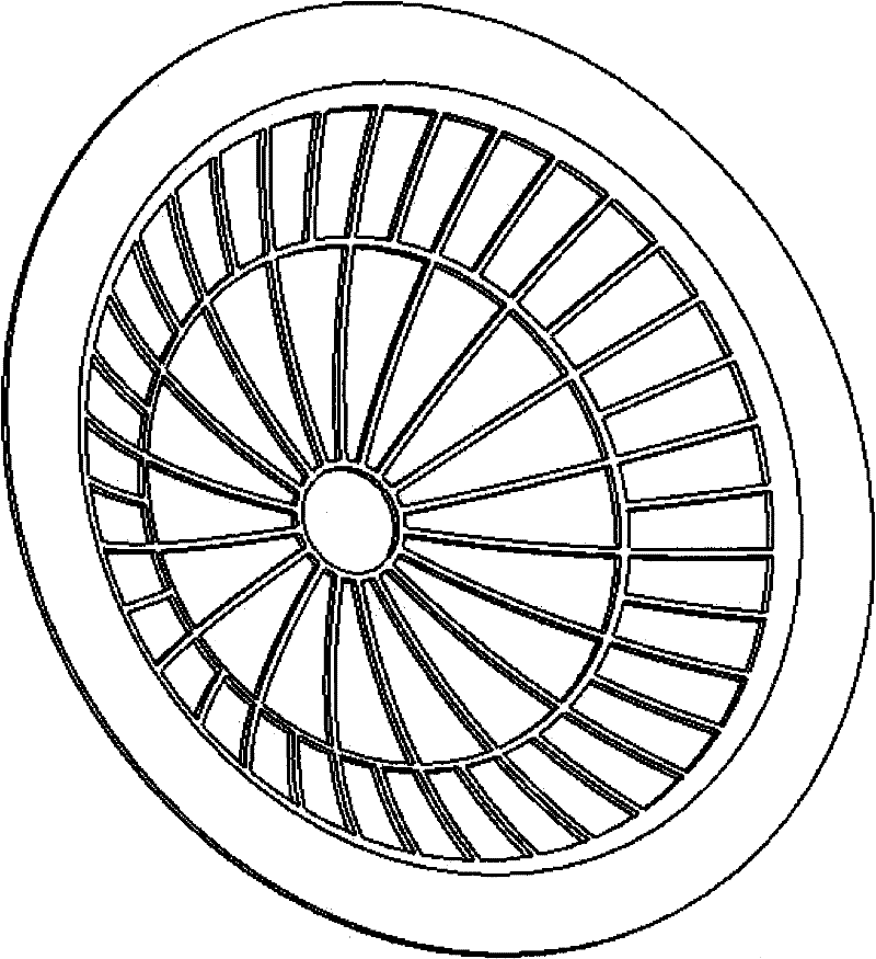

Image

  • Method for inhibiting grid emission of pulsed travelling wave tube
  • Method for inhibiting grid emission of pulsed travelling wave tube
  • Method for inhibiting grid emission of pulsed travelling wave tube

Examples


Embodiment Construction

[0023] A method for suppressing grid emission of a pulse traveling wave tube of the present invention directly uses hafnium (Hf) as grid material. Hafnium is also a high-temperature electric vacuum material, but its plastic processing performance is worse than that of molybdenum. However, after strictly controlling the annealing process and a series of process operation procedures, the yield of finished products can be effectively improved. In addition, it needs to be emphasized that due to the fact that hafnium can combine with H at a certain temperature 2 , O 2 , N 2 Therefore, it is necessary to pay attention to the ambient atmosphere at high temperature, so as to avoid the change of the material form of hafnium in a certain high temperature and certain atmosphere, resulting in a significant decrease in the mechanical strength of the grid.

[0024] A method for suppressing the grid emission of a pulsed traveling wave tube of the present invention, particularly relates to ...


PUM

PropertyMeasurementUnit
Thicknessaaaaaaaaaa

Abstract

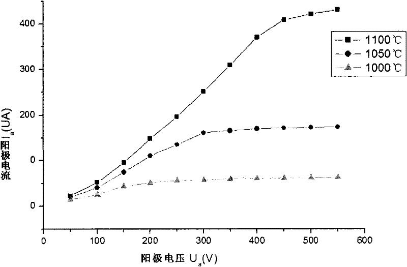
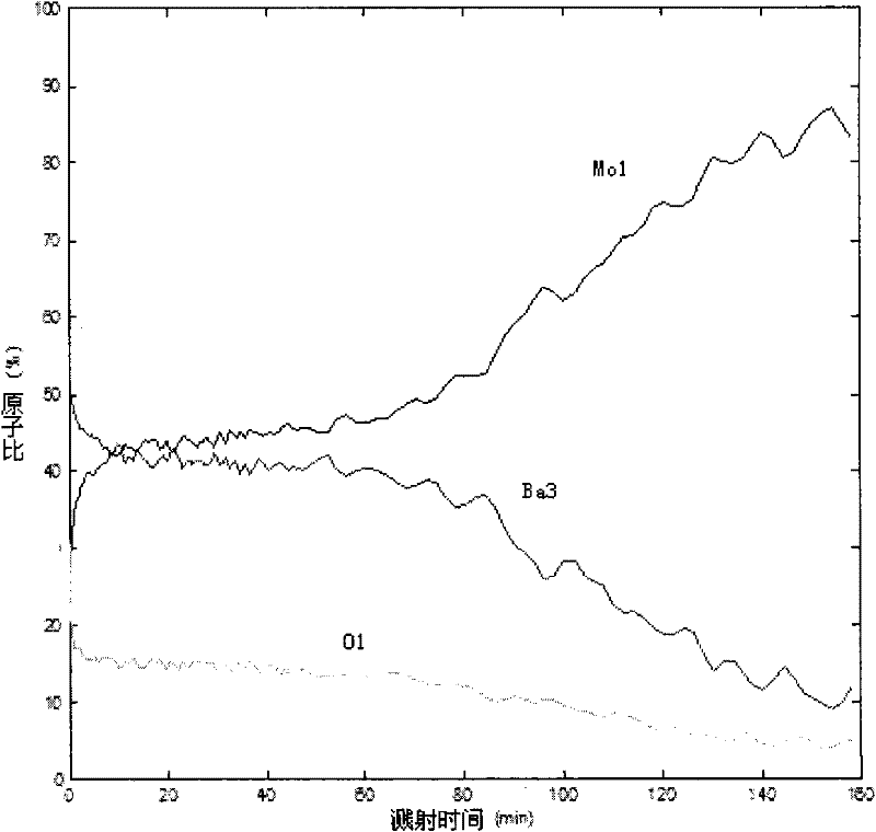
The invention discloses a method for inhibiting grid emission of a pulsed travelling wave tube, relates to a microwave electric vacuum technology, and states an improvement measure for effectively inhibiting grid thermionic emission (grid emission for short) of the pulsed travelling wave tube, namely a novel hafnium (Hf) material is used as the material of a grid net in a pulsed travelling wave tube electronic gun. The metal has the properties of high work function, low secondary electron yield and high melting point / low saturated steam pressure; and a diode test and tests of physical analysis, tube preparation application and the like of the metal show that the hafnium metal foil serving as a grid net substrate material can inhibit grid emission of the conventional pulsed travelling wave tube during the operating life, so that the operating reliability and the operating stability of the grid-controlled pulsed travelling wave tube is powerfully guaranteed.

Description

technical field [0001] The invention relates to the field of microwave electric vacuum technology, and relates to a method for suppressing grid emission of a pulse traveling wave tube, which realizes the goal of suppressing grid thermionic emission and improves the working reliability and stability of the pulse traveling wave tube. Background technique [0002] At present, grid-controlled pulse traveling wave tubes are widely used in key national defense projects such as radar and electronic countermeasures. Emitting, so that the traveling wave tube works in a pulse modulation state with a certain pulse width and repetition frequency, and realizes pulse output with high peak power. [0003] In the electron gun of the grid-controlled pulse traveling wave tube, the grid is used to play the role of the control electrode. The control electrode itself should not emit electrons. If the control electrode emits electrons, it will disturb the injection of electrons emitted from the c...

Claims


Application Information

Patent Timeline
IPC IPC(8): H01J25/02H01J25/36
Inventor 姚刘聪苏小保吕薇王小霞
Owner INST OF ELECTRONICS CHINESE ACAD OF SCI
Learn More