

Liquid crystal display device
A technology of liquid crystal display device and display surface, which is applied in identification devices, optics, instruments, etc., and can solve the problems of blackening and invisible.
- Summary
- Abstract
- Description
- Claims
- Application Information
AI Technical Summary
Problems solved by technology
Method used
Image

Examples
Embodiment approach 1
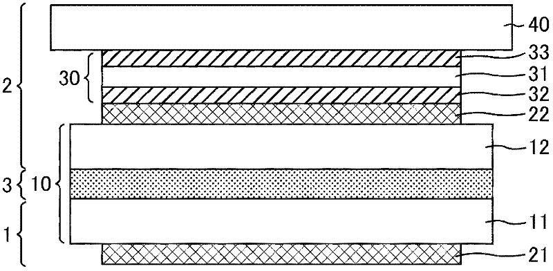
[0052] figure 1 It is a schematic cross-sectional view of the liquid crystal display device of the first embodiment. Such as figure 1 As shown, the liquid crystal display device of Embodiment 1 includes a first substrate 1 , a liquid crystal layer 3 , and a second substrate 2 in this order toward the display surface side. That is, the second substrate 2 is disposed on the display surface side with the liquid crystal layer 3 interposed therebetween, and the first substrate 1 is disposed on the inner side (rear side) of the liquid crystal display device. In addition, the liquid crystal display (LCD) panel 10 includes: an array substrate 11 included in the first substrate 1 , a liquid crystal layer 3 , and a counter substrate 12 included in the second substrate 2 .
[0053] The liquid crystal layer 3 includes a liquid crystal material having a characteristic of being aligned in a specific direction by applying a certain voltage. The type of liquid crystal material is not parti...
Embodiment approach 2
[0085] Figure 6 It is a schematic cross-sectional view of a liquid crystal display device according to Embodiment 2. FIG. Such as Figure 6 As shown, the liquid crystal display device of Embodiment 2 has a first substrate 1, a liquid crystal layer 3, and a second substrate 2 in order toward the display surface side, and the array substrate 11, the liquid crystal layer 3, and the second substrate 2 provided by the first substrate 1 The point that the counter substrate 12 included in the substrate 2 constitutes the LCD panel 10 is the same as that of the liquid crystal display device in Embodiment 1, but the point that the double-sided adhesive tape 30 included in the second substrate 2 includes only the adhesive layer 34 is the same as that of the liquid crystal display device in Embodiment 1. The liquid crystal display device of Embodiment 1 is different. That is, in Embodiment 2, the second substrate is provided in order toward the direction away from the liquid crystal la...
Embodiment approach 3
[0105] Figure 7 It is a schematic cross-sectional view of a liquid crystal display device according to Embodiment 3. FIG. Such as Figure 7 As shown, the liquid crystal display device according to Embodiment 3 includes a first substrate, a liquid crystal layer, and a second substrate in sequence toward the display surface side, and is formed by the array substrate 11, the liquid crystal layer 3, and the second substrate 2 included in the first substrate 1. The counter substrate 12 provided is the same as the liquid crystal display device of the first embodiment in that the LCD panel 10 is formed, but the liquid crystal display device of the first embodiment is the same in that the intermediate layer of the second substrate 2 includes the capacitive touch panel 60 as a constituent element. The display device is different. That is, in Embodiment 3, the second substrate is provided in order toward the direction away from the liquid crystal layer 3, that is, toward the display ...
PUM
| Property | Measurement | Unit |
|---|---|---|
| thickness | aaaaa | aaaaa |
| thickness | aaaaa | aaaaa |
| thickness | aaaaa | aaaaa |
Abstract
Description
Claims
Application Information