Worm-type plastic corrugated pipe grooving machine

A corrugated pipe and slotting machine technology, applied in metal processing, etc., can solve the problems of reducing scrap rate and slotting efficiency, volume and cost reduction, etc., to achieve increased production efficiency, reduced product scrap rate, and high slotting quality Effect

Inactive Publication Date: 2012-05-16
ZHANGJIAGANG BEIER MACHINERY
View PDF7 Cites 44 Cited by
  • Summary
  • Abstract
  • Description
  • Claims
  • Application Information

AI Technical Summary

Problems solved by technology

[0003] In order to overcome the shortcomings of existing plastic corrugated pipe slotting machines in use, the present invention provides a worm screw type plastic corrugated pipe slotting machine, which does not require any pipe conveying device and photoelectric sensor The switch induction counting system realizes the function of conveying the plastic corrugated pipe through the engagement of the worm curve fixed on the slotting knife rod with the peak of the plastic corrugated pipe, and realizes the plastic corrugated pipe through an alloy cutter head installed at the end of the worm curve. The trough of the pipe is grooved, the mechanical structure is very simple, the volume and cost of the machine are greatly reduced, and the independent pipe conveying device and electronic and electrical induction control system are omitted, the position of the groove is very accurate, and the quality of the groove is greatly improved. Greatly reduced scrap rate and slotting efficiency

Method used


Image

  • Worm-type plastic corrugated pipe grooving machine
  • Worm-type plastic corrugated pipe grooving machine

Examples


Embodiment Construction

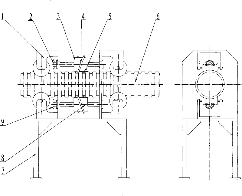
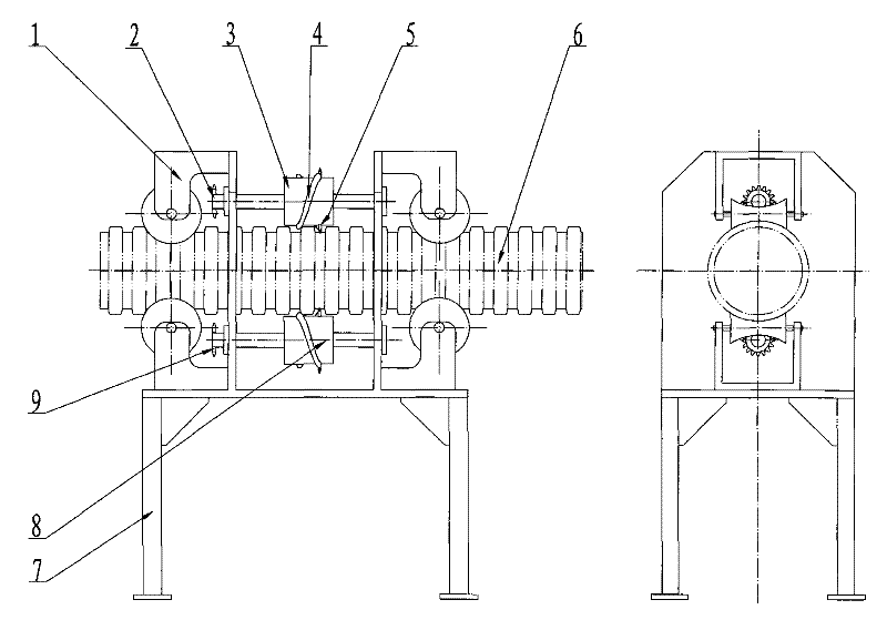
[0013] The plastic corrugated pipe (6) is clamped by two sets of guide wheels (1) for center positioning, and can move axially forward and backward. The upper knife bar (3) and the lower knife bar (8) are respectively fixed with forward and reverse rotation Worm screw curve (4), the end of worm screw curve (4) is respectively equipped with a piece of alloy cutter head (5), the crest of worm screw curve (4) and plastic corrugated pipe (6) engages, upper cutter bar (3) and lower cutter bar ( The two ends of 8) are supported on the front and rear wall panels on the frame (7) through bearings, and the upper drive sprocket (3) and the lower drive sprocket (3) are respectively installed on the front of the upper knife bar (3) and the lower knife bar (8). Sprocket wheel (9), input a direction of rotation opposite to upper transmission sprocket wheel (3) and lower transmission sprocket wheel (9) respectively, the same power of rotating speed, positive on the upper cutter bar (3) and lo...


PUM


Abstract

The invention relates to a worm-type plastic corrugated pipe grooving machine. Function of conveying plastic corrugated pipes is completed by a worm curve fixed on a cutter bar of a grooving cutter; the functions of cutting and grooving are realized by one alloy cutter head arranged at the terminal of the worm curve, the worm curve is meshed with wave crests of the plastic corrugated pipes, the plastic corrugated pipes advance for one pitch when being pushed by the worm curve once the cutter bar rotates for a circle, namely the plastic corrugated pipes advance to the next wave crest from the current wave crest, the alloy cutter head arranged at the terminal of the worm curve carries out grooving on the current wave crest for once, the alloy cutter head arranged at the terminal of the worm curve is vertical to axes of the plastic corrugated pipes to ensure that a blade is in a cutting interval while the plastic corrugated pipes do not axially move, the plastic corrugated pipes continuously axially move along with rotation of the cutter bar, and the blade carries out grooving on the wave crest one by one. The grooving machine provided by the invention has simple mechanical structure, no independent pipe conveying device or electronic and electrical inductive control system is required, grooving position is accurate, grooving quality is greatly improved, and rejection rate is greatly reduced while grooving efficiency is greatly improved.

Description

Technical field [0001] The invention relates to a mechanical device used for slotting in the outer circumferential direction of the trough of the plastic corrugated pipe, especially it does not require any electronic and electrical induction control system, and can be positioned very precisely only through the transmission mechanism of the machine itself. A slotting machine that strictly guarantees that each slot is located in the center of the trough of the corrugated pipe. Background technique [0002] At present, the known plastic corrugated pipe slotting machine is composed of several groups of cutting saws located on the same circumference, and the several groups of cutting saws are respectively driven by several pull rods to feed or withdraw towards the center direction, and the head and tail of the several pull rods are hinged to each other. Together and driven by the same oil cylinder, each cutting saw group is always synchronized each time it feeds or withdraws towa...

Claims


Application Information

Patent Timeline
Patent Type & Authority Applications(China)
IPC IPC(8): B26D3/06B26D7/26B26D7/06B26D7/01
Inventor 何德方邓少东
Owner ZHANGJIAGANG BEIER MACHINERY
Why Eureka
Try Eureka