Conveying device and system

A technology of conveying device and driving device, which is applied to conveyor objects, transportation and packaging, furnaces, etc., to achieve the effects of long service life, simple logic control optimization, and easy and precise control.

Active Publication Date: 2015-01-14
BEIJING NAURA MICROELECTRONICS EQUIP CO LTD
View PDF4 Cites 0 Cited by
  • Summary
  • Abstract
  • Description
  • Claims
  • Application Information

AI Technical Summary

Problems solved by technology

Due to the difficulty in optimizing the front-end logic control of the robotic arm, and the force changes of each connecting rod and bearing when picking up and placing the wafer is relatively large, and the force situation is also relatively complicated, resulting in poor performance of the reciprocating motion of the transfer device, Allows for short conveyor maintenance periods and short life

Method used


Image

  • Conveying device and system
  • Conveying device and system
  • Conveying device and system

Examples


Embodiment Construction

[0027] In order to enable those skilled in the art to better understand the technical solutions of the present invention, the embodiments provided by the present invention will be described in detail below in conjunction with the accompanying drawings.

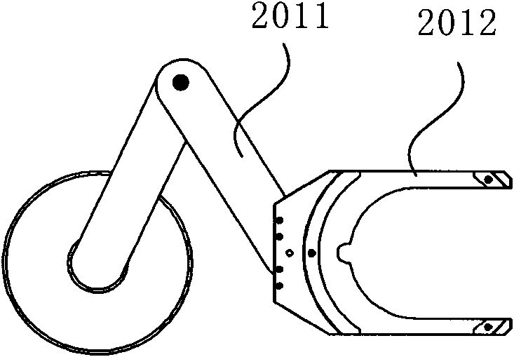
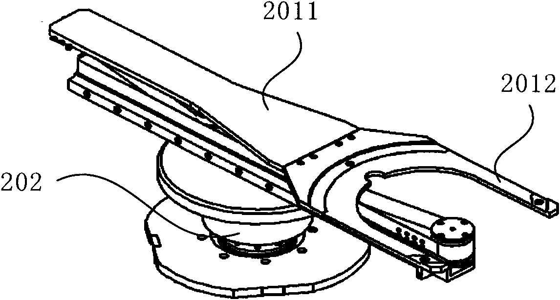
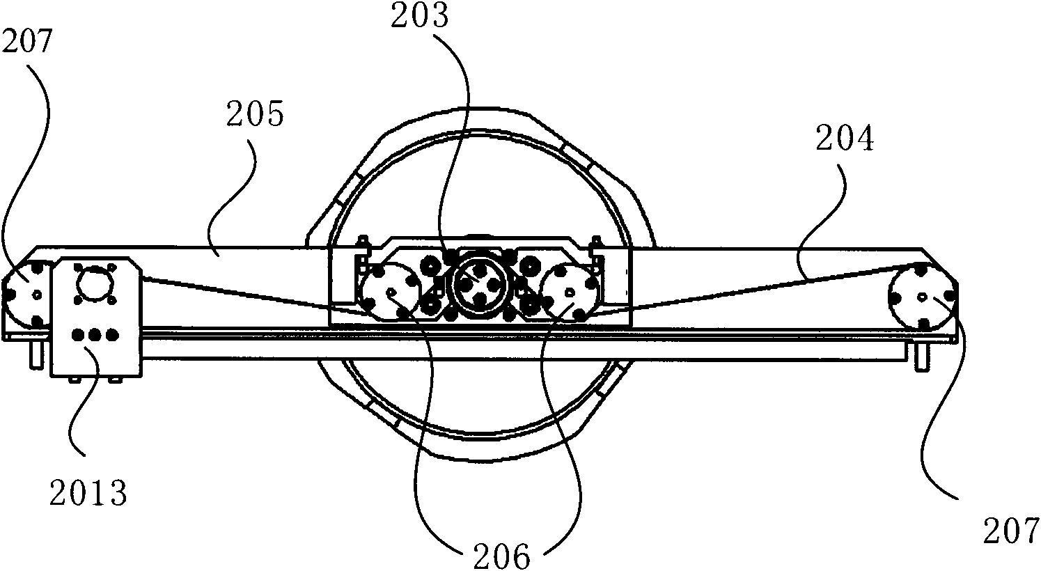
[0028] figure 2 It is a perspective view of the first embodiment of the conveying device provided by the present invention, image 3 It is a top view of the first embodiment of the conveying device provided by the present invention, Figure 4 It is a schematic structural diagram of the bracket in the first embodiment of the delivery device provided by the present invention. combine figure 2 , image 3 with Figure 4 As shown, the transmission device in this embodiment includes: a mechanical arm, a first driving device 202, a friction wheel ( figure 2 not shown in ) and a rotating belt 204, wherein the mechanical arm includes a fixedly connected extension piece 2011, a support piece 2012 and a support piece 2013, one en...


PUM


Abstract

The invention provides a conveying device and system. The device comprises a mechanical arm, a first drive device, a friction wheel and a rotation belt, wherein the friction wheel is fixed on a rotating shaft of the first drive device; the rotation belt is driven by the friction wheel to move via the friction between the friction wheel and the rotation belt; and the rotation belt is fixedly connected with the mechanical arm. The device and the system have the following beneficial effects: by driving the friction wheel to drive the rotation belt to move to drive the mechanical arm to reciprocate, not only can the logic control optimization of the mechanical arm be simple, but also the characteristics of zero clearance and good repeatability exist between the friction wheel and the rotation belt; the position and movement locus of the mechanical arm are easier to control accurately; and when the mechanical arm takes or puts wafers, the external forces borne by the mechanical arm, the friction wheel, tension wheels, guide wheels and other parts do not change obviously, so that the conveying device has the advantages of long maintenance time interval and long service life.

Description

technical field [0001] The present invention relates to semiconductor manufacturing technology, in particular, to a transmission device and system. Background technique [0002] In semiconductor, liquid crystal, or LED manufacturing industries, an automatic transfer device that can accurately pick and place wafers in an atmosphere or a vacuum environment is required, and the transfer device usually includes a robot arm and a driving device. [0003] figure 1 It is a structural schematic diagram of the mechanical arm in the existing conveying device. like figure 1 As shown, the structure of the mechanical arm of the transmission device generally adopts the Scara (Selective Compliance Assembly Robot Arm, Selective Compliance Assembly Robot Arm) connecting rod method. The above-mentioned connecting rod method is usually a cantilever beam structure. Through the bearing connection, the synchronous belt is installed inside the mechanical arm to realize rotation and expansion...

Claims


Application Information

Patent Timeline
Patent Type & Authority Patents(China)
IPC IPC(8): B65G49/07B65G47/90
Inventor 周卫国
Owner BEIJING NAURA MICROELECTRONICS EQUIP CO LTD
Why Eureka
Try Eureka