
Video monitoring system and moving target detecting and tracking method thereof

A video monitoring system and moving target technology, which can be used in closed-circuit television systems, image data processing, instruments, etc., can solve the problems of difficult to extract stable feature points, intelligent video monitoring constraints, and inability to extract feature points, etc.

Active Publication Date: 2012-05-16
SHENZHEN ZTE NETVIEW TECH
View PDF2 Cites 34 Cited by
  • Summary
  • Abstract
  • Description
  • Claims
  • Application Information

AI Technical Summary

Problems solved by technology

[0002] In the traditional intelligent video monitoring system, most of the monitoring cameras are fixed cameras, the background image is fixed, and the foreground target is moving. The problem existing in the application of this system is: in some pre-set positions, the moving target is easily exceeded. Monitoring the field of view but not continuous tracking, these conditions make the application of traditional intelligent video surveillance greatly restricted
Although the color feature is a very useful feature, when the color of the object and the background color are similar, it is often difficult to use only the color to track, and it is easy to cause tracking errors. Some researchers use a variety of feature fusion methods to select features; Using SIFT, the SURF feature is relatively stable as the feature information of the tracked target, and has strong adaptability to changes in background color and illumination. It is an ideal target feature expression method. The disadvantage is that it may be difficult to extract for a small number of targets. Stable feature points or even feature points cannot be extracted

Method used


Image

  • Video monitoring system and moving target detecting and tracking method thereof
  • Video monitoring system and moving target detecting and tracking method thereof
  • Video monitoring system and moving target detecting and tracking method thereof

Examples


Embodiment Construction

[0055] In order to make the object, technical solution and advantages of the present invention clearer, the present invention will be further described in detail below in conjunction with the accompanying drawings and embodiments. It should be understood that the specific embodiments described here are only used to explain the present invention, not to limit the present invention.

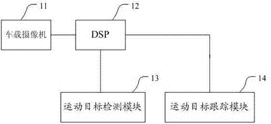
[0056] see figure 1 , the video monitoring system provided by the present embodiment mainly includes: vehicle-mounted camera 11, DSP12, moving object detection module 13 and moving object tracking module 14; If there is a moving object, the moving object tracking module 14 is invoked to track the moving object. The specific process includes: moving object detection, moving object model building, and moving object tracking.

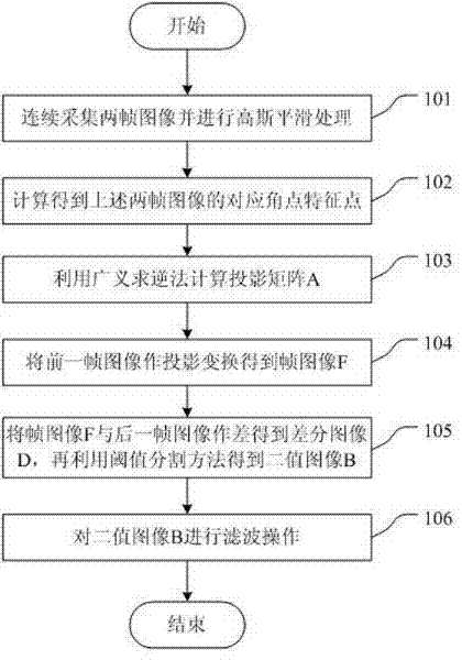
[0057] Among them, (1) such as figure 2 As shown, the steps of moving target detection specifically include:

[0058] Step 101, collecting two consecutive frames of images ...


PUM


Abstract

The invention discloses a video monitoring system and a moving target detecting and tracking method thereof. The method is applied to the video monitoring system on the condition that a camera is in a moving state. The method comprises the following steps: a moving target detection step, in which combination of a Harris corner and an HOG descriptor is employed as an image feature as well as processing including image feature extraction, image projection conversion, and image subtraction operation and the like is carried out to obtain a plurality of moving targets; a moving target model establishment step, in which moving target models are established for all the moving targets as well as a combination mode of a Harris corner, an extreme point and an HOG descriptor is employed to express features of the moving targets; and a target tracking step, in which target tracking is carried out according to the moving target models. According to the invention, corner feature matching is employed to reduce the calculated amount and precision of moving target detection is ensured; a corner and an extreme point are employed as target features, so that target identification has high robustness and tracking sustainability is strong; and a target motion estimation method is employed to reduce the calculated amount.

Description

technical field [0001] The invention relates to the technical field of video monitoring, in particular to a video monitoring system and a moving target detection and tracking method applied in the case of camera movement. Background technique [0002] In the traditional intelligent video monitoring system, most of the monitoring cameras are fixed cameras, the background image is fixed, and the foreground target is moving. The problem existing in the application of this system is: in the cyclic monitoring of certain preset positions, the moving target is easy to exceed Monitoring the field of view but not continuous tracking, these conditions make the application of traditional intelligent video surveillance greatly restricted. The motion camera monitoring can overcome the defects of the above-mentioned traditional camera monitoring, and it can be applied to vehicle monitoring, PTZ (Pan Tilt Zoom, camera pan tilt rotation, pitch movement and lens zoom) target tracking, intell...

Claims


Application Information

Patent Timeline
IPC IPC(8): G06T7/20H04N7/18
Inventor 张巍苏鹏宇唐李卉谢斌周锐鹏
Owner SHENZHEN ZTE NETVIEW TECH
Learn More