Reaction device for fluidized bed catalyst performance evaluation
A fluidized bed catalyst and reaction device technology, applied in organic chemistry, chemical recycling, bulk chemical production, etc., can solve the problems of single type of device and difficulty in flexible adjustment of uses, achieve good technical effects, expand uses, and can be used The effect of flexible adjustment
- Summary
- Abstract
- Description
- Claims
- Application Information
AI Technical Summary
Problems solved by technology
Method used
Image

Examples
Embodiment 1
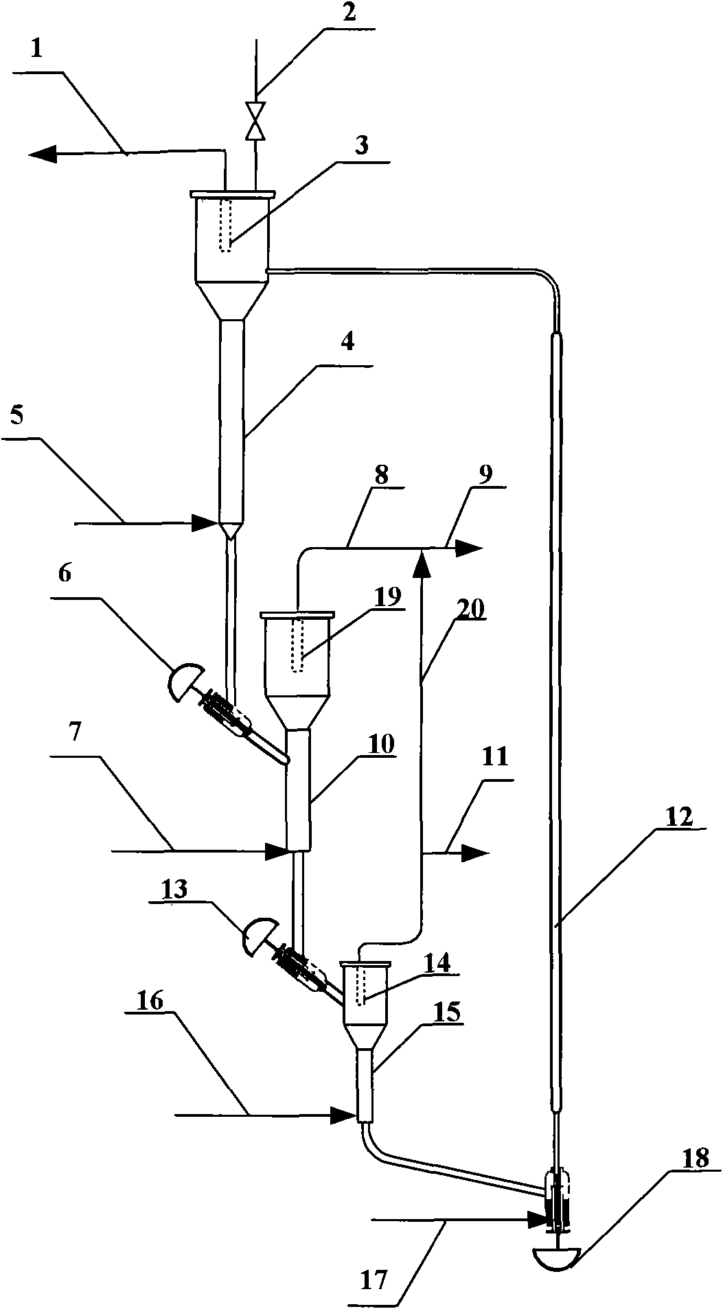
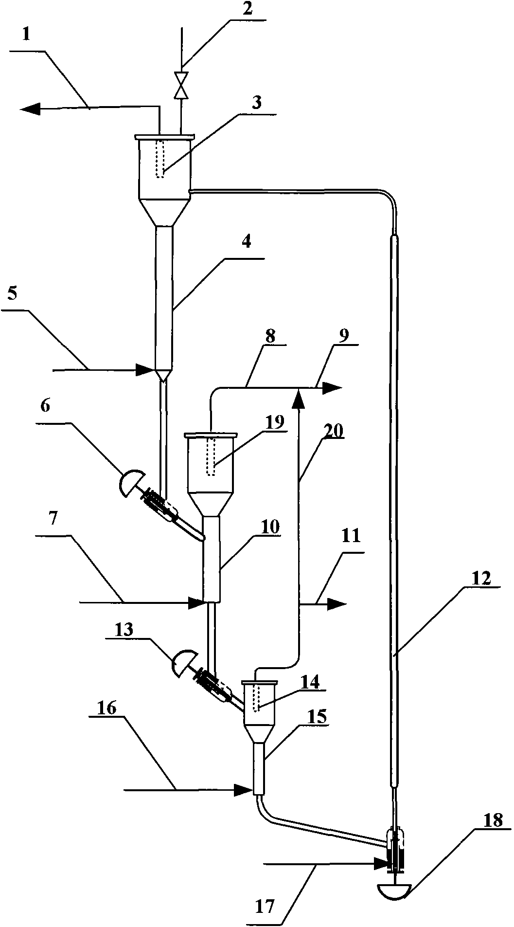
[0017] in such as figure 1 In the reaction device shown, there are gas outlets on the top of the regenerator, the first reactor, and the second reactor, and catalyst filters are arranged before the gas outlets, and the catalyst flow control valve is a plug valve, and the outlet of the catalyst flow control valve is connected to the first The dense-phase section of a reactor is connected, the outlet of the riser is connected with the dilute-phase section of the regenerator, and a catalyst feeding pipeline is arranged on the top of the regenerator. The operating pressure of the device is normal pressure (gauge pressure), the catalyst adopts SAPO-34, the first raw material adopts mixed hydrocarbons with more than four carbons, and wherein the content of carbon four olefins is 88% (weight), and the second raw material adopts methanol with a purity of 99.5%. The regeneration medium is air, the regeneration temperature is 650°C, the reaction temperature of the first reactor is 550°C...
Embodiment 2
[0019] According to the conditions and steps of Example 1, only the first raw material adopts methanol with a purity of 99.5%, the second raw material adopts steam, the second reactor is used as a stripper, the first reactor reaction temperature is 470 ° C, and the quality of methanol Airspeed is 4.2 hours -1 , the catalyst carbon deposit mass fraction that comes out from the bottom of the first reactor is 4.3%, and enters riser after stripping, and ethylene and propylene carbon base yield are 81.28% (weight) in the gas phase product.
[0020] Apparently, the device of the present invention can be used for continuous reaction-regeneration performance evaluation of fluidized bed catalysts. The device is novel in type, flexible in use, has great technical advantages, and can be used in performance evaluation of fluidized bed catalysts.
PUM
 Abstract
Description
Claims
Application Information
 - Generate Ideas
- Intellectual Property
- Life Sciences
- Materials
- Tech Scout
- Unparalleled Data Quality
- Higher Quality Content
- 60% Fewer Hallucinations
Browse by: Latest US Patents, China's latest patents, Technical Efficacy Thesaurus, Application Domain, Technology Topic, Popular Technical Reports.
© 2025 PatSnap. All rights reserved.Legal|Privacy policy|Modern Slavery Act Transparency Statement|Sitemap|About US| Contact US: help@patsnap.com