Systems and methods for determining the target thermal conditioning value to control a rechargeable energy storage system

A technology of heat regulation and recharging, applied in the power supply, power management, control devices, etc. of electric heating circuits, which can solve the problems that hinder the effective operation of RESS and link them together

Inactive Publication Date: 2012-05-23
GM GLOBAL TECH OPERATIONS LLC
View PDF5 Cites 28 Cited by
  • Summary
  • Abstract
  • Description
  • Claims
  • Application Information

AI Technical Summary

Problems solved by technology

[0007] Although temperature can be easily measured, it is difficult to correlate this temperature with the method of driving one or more high voltage devices for RESS heating or cooling
This in turn hampers the efficient operation of the RESS, as well as the ability to operate the RESS in a manner that avoids temperature-related component failures

Method used


Image

  • Systems and methods for determining the target thermal conditioning value to control a rechargeable energy storage system
  • Systems and methods for determining the target thermal conditioning value to control a rechargeable energy storage system
  • Systems and methods for determining the target thermal conditioning value to control a rechargeable energy storage system

Examples


Embodiment Construction

[0073] Before referring to the drawings, which illustrate several embodiments in detail, it is to be understood that the application is not to be limited to the details or methodology described in the description or shown in the drawings. It should also be understood that the terminology used is for the purpose of description only and should not be regarded as limiting.

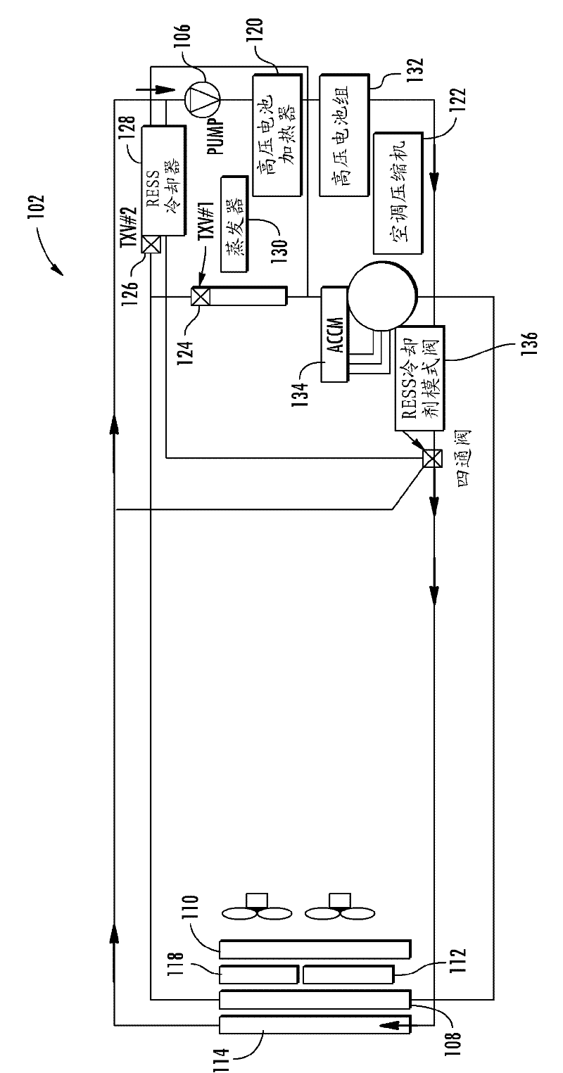
[0074] now refer to figure 1 , shows a thermal hardware diagram of the RESS 102 according to an embodiment. The RESS may include an air conditioner condenser 108 , a power electronics radiator 118 , a RESS radiator 114 , an internal combustion engine (ICE) radiator 110 , and a transmission oil radiator 112 . The RESS may include portions having an evaporator 130 , which may be located in the vehicle passenger compartment, and other system components that may be located in the engine compartment of the vehicle. The other system components may include a thermal expansion valve (TXV #1 ) 124 for controlling th...


PUM


Abstract

Systems and methods for determining the target thermal conditioning value to control a rechargeable energy storage system. Target thermal conditioning values are determined using a required thermal power value and a heat generation value in order to appropriately condition the RESS for heating and cooling.

Description

[0001] This application claims priority to Provisional Application No. 61 / 407,742, filed October 28, 2010, the contents of which are incorporated herein by reference. [0002] This invention was made with support under Government Contract No. DE-EE0002217 awarded by the Department of Energy. The government has certain rights and interests in this invention. technical field [0003] The present application relates generally to determining a target thermal regulation value for controlling a rechargeable energy storage system (RESS), and more particularly to systems and methods for determining a target thermal regulation value using thermal power and heat generation values. Background technique [0004] Automotive technology is rapidly advancing in the search for alternatives to gasoline as the primary energy source for vehicle propulsion systems. Many of these advances utilize hybrid electromechanical systems that recover some of the mechanical energy of combustion engines as...

Claims


Application Information

Patent Timeline
Patent Type & Authority Applications(China)
IPC IPC(8): B60L11/18B60R16/02B60L50/16
CPCY02T10/7291Y02T10/7005B60L11/1874H01M10/48H01M10/5006Y02T10/7077H01M10/5022B60L11/14B60L1/003B60L2240/549B60L2260/56H01M10/502B60L11/1875B60L2240/545H01M10/5004B60L1/02B60L2240/445H01M10/5016H01M10/486B60L2250/16B60L2240/36Y02T10/7011Y02T90/16B60W20/00H01M10/5083Y02T10/705H01M10/5079Y02E60/12B60L2240/662Y02T10/70H01M10/625H01M10/63H01M10/615H01M10/633H01M10/6569H01M10/6571H01M10/613B60L50/16B60L58/26B60L58/27Y02T10/72Y02T10/7072Y02E60/10
Inventor M.西莫尼尼
Owner GM GLOBAL TECH OPERATIONS LLC
Why Eureka
Try Eureka