
Fuel injection nozzle for internal combustion engine, nozzle blank and manufacturing method thereof

A technology of fuel injection and manufacturing method, which is applied to fuel injection devices, special fuel injection devices, mechanical equipment, etc., can solve the problems of high material cost, difficult-to-process materials, and reduced productivity of fuel injection nozzles, and achieve low-cost size Accuracy, productivity improvement, and effect of shortening machining process

Active Publication Date: 2012-05-23
NIPPON PISTONRING CO LTD +1
View PDF9 Cites 9 Cited by
  • Summary
  • Abstract
  • Description
  • Claims
  • Application Information

AI Technical Summary

Problems solved by technology

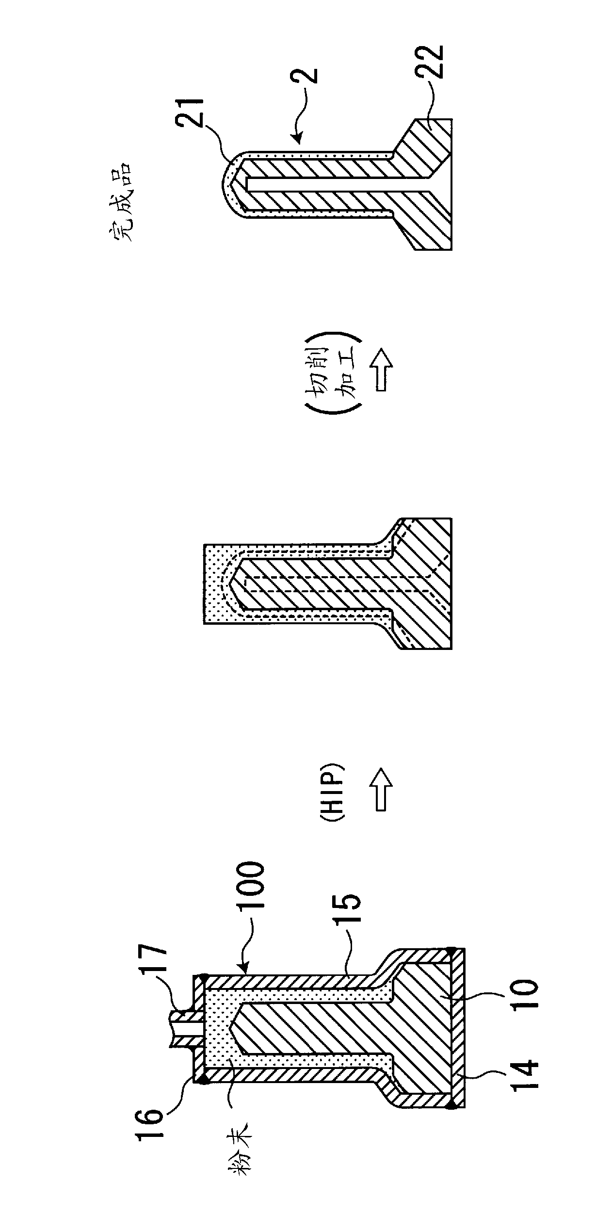
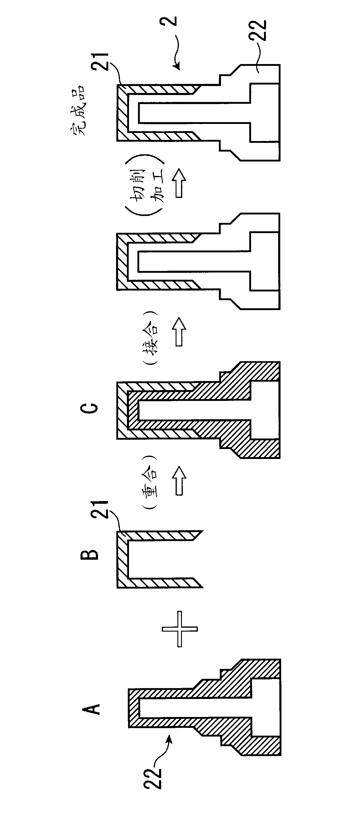
[0018] However, in this method, a large amount of expensive materials constituting the outer cover (nozzle tip portion outer surface member) 21 is used, and most of them need to be removed by machining, so that the material cost becomes high, and there is a possibility that the manufacturing cost of the fuel injection nozzle becomes lower. high problem
In addition, the material constituting the outer cover (the outer surface of the tip of the nozzle) is often a hard and difficult-to-machine material, which requires a long time for machining, and there is a problem that the productivity of the fuel injection nozzle decreases.

Method used


Image

  • Fuel injection nozzle for internal combustion engine, nozzle blank and manufacturing method thereof
  • Fuel injection nozzle for internal combustion engine, nozzle blank and manufacturing method thereof
  • Fuel injection nozzle for internal combustion engine, nozzle blank and manufacturing method thereof

Examples


Embodiment

[0063] Two kinds of raw material powders produced by the water spray method were prepared. In addition, as the raw material powder, a raw material powder having an average particle diameter of 5 to 15 μm is used. One kind of raw material powder is SKD61 steel powder, which is used for the nozzle body. The other raw material powder is Ni-based superalloy powder, which is used for the outer parts of the tip of the nozzle. The composition of SKD61 steel is: 0.35%C-0.97%Si-0.40%Mn-4.93%Cr-1.21%Mo-1.01%V-bal.Fe in terms of mass%. In addition, the composition of the Ni-based superalloy in terms of mass % is: 0.02%C-0.18%Si-0.23%Mn-21.8%Cr-8.9%Mo-3.9%Nb-2.4%Fe-bal.Ni.

[0064] A binder was blended in 40% by volume of the raw material powder, and mixed and stirred at a temperature of 120 to 180° C. to form a kneaded product for injection molding. The adhesive is used by mixing a wax component (PW), a plastic component (PE), and a vegetable oil component (peanut oil) and heating and...


PUM


Abstract

Provided are a fuel injection nozzle for an internal combustion engine, a nozzle blank, and a manufacturing method for the nozzle blank, wherein the production processes are simple, the productivity is high, and the production can be performed at a low cost and with a high precision. A fuel injection nozzle for an internal combustion engine has a two layer structure of different materials, comprised of a nozzle body and a nozzle tip outer surface member which is arranged to cover a tip outer surface side of the nozzle body. The nozzle body is formed of a mold which has been molded into a predetermined shape by a metal powder injection molding method and which has been subjected to degreasing to obtain a degreased body forming the nozzle body. Likewise, separately, the nozzle tip outer surface member is formed of a mold which has been molded into a predetermined shape by a metal powder injection molding method and which has been subjected to degreasing to obtain a degreased body forming the nozzle tip outer surface member. The degreased body forming the nozzle tip outer surface member is superimposed on the degreased body forming the nozzle body to cover the tip outer surface side of the degreased body forming the nozzle body and is subjected to diffusion sintering to thereby integrally unite them. It is preferable that a hot isostatic pressing operation be performed after the diffusion sintering.

Description

technical field [0001] The present invention relates to a nozzle for fuel injection of an internal combustion engine, and relates to a highly durable and inexpensive fuel injection nozzle suitable for use in an internal combustion engine, particularly a diesel engine, a nozzle blank, and a manufacturing method thereof. Background technique [0002] As for the fuel injection nozzle 1 disposed in the combustion chamber of an internal combustion engine for a ship or the like, conventionally, the following methods have been used, such as Figure 5 The structure shown in the cross-sectional view of: a nozzle head (nozzle) 2 having an injection port 2a formed at one end and a valve seat 4 of a needle valve 3 formed at the other end; and the nozzle head ( The needle valve 3 arranged in contact with the valve seat 4 of the nozzle 2 can inject fuel supplied from a fuel tank (not shown) through the fuel passage 1 a from the injection port 2 a at predetermined timing. Therefore, the no...

Claims


Application Information

Patent Timeline
IPC IPC(8): F02M61/18B22F3/02B22F3/15B22F7/06F02M61/16C22C19/05C22C38/00C22C38/24
CPCF02M61/168C22C38/34B22F2998/10C22C19/05F02M2200/8046C22C38/04B22F7/062C22C38/22C22C19/055C22C38/24B22F3/225B22F3/1021B22F3/10B22F3/15F02M61/18F02M61/16B22F3/02
Inventor 木村正宏新泽真洋青木敦也大宫隆雄后藤贵幸
Owner NIPPON PISTONRING CO LTD
Learn More