Sensing device

A technology of detection equipment and detectors, which is applied in the direction of testing/calibration of speed/acceleration/shock measurement equipment, measuring devices, measuring devices, etc., and can solve problems such as increasing system costs and error detection

Inactive Publication Date: 2012-05-23
MITSUBISHI ELECTRIC CORP
View PDF8 Cites 11 Cited by
  • Summary
  • Abstract
  • Description
  • Claims
  • Application Information

AI Technical Summary

Problems solved by technology

However, the disadvantage of double pulse encoders is that if one of the detectors fails, detection of the direction of motion is no longer possible (two shift signals are required for direction of motion detection and one for speed detection)
Another disadvantage is that error detection based on the current state is impossible since there is no invalid state in the current state
However, this system requires two identical encoders to be installed on the same shaft, which will significantly increase the cost of the system
Also, it must be ensured that the encoder is precisely aligned

Method used


Image

  • Sensing device
  • Sensing device
  • Sensing device

Examples


Embodiment Construction

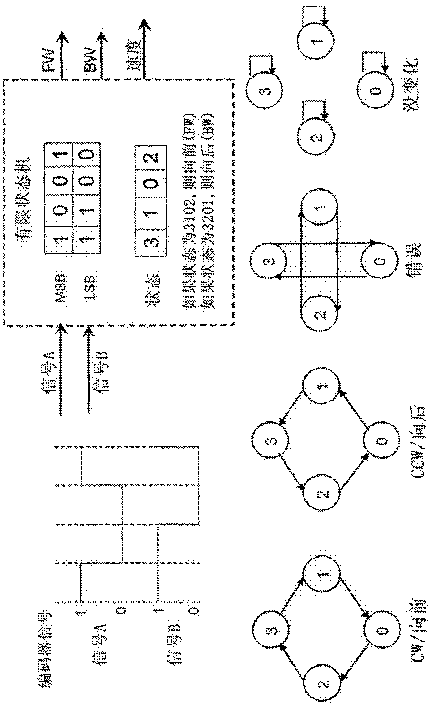
[0039] An example of state transitions and dominant states of an encoder with dual detectors (prior art) has been described in the background of the invention and is given by figure 1 It is shown that the encoder generates double pulses staggered by 90 degrees.

[0040] exist figure 1 In , assign a value to each encoder state, namely the decimal state (3, 1, 0, and 2). If the state transitions to: eg figure 1 3 to 1 to 0 to 2 shown in , then the direction of motion is clockwise (CW), ie forward or upward. If the state transition is reversed (see figure 1 ), the direction of motion is counterclockwise (CCW), that is, backward or downward.

[0041] figure 1 Invalid transitions between different states are also shown in , which can also be used for error detection (prior art). However, the main disadvantage is that there is no error detection based on the current state (only transitions from invalid states) since there is no invalid state in the current state.

[0042] To ...


PUM


Abstract

The present invention discloses a speed and movement direction sensing device. The sensing device includes an incremental encoder, which generates three pulses shifted by about 120 (electrical) degrees. A speed signal generation section receives the encoder signals and generates a pulse signal, which frequency is proportional with the frequency of the input signal. The encoder self-test section monitors the encoder states and detects encoder error based on the encoder signals and a direction detection section generates a direction signal based on the encoder pulses. The sensing device allows encoder self-test even in case of zero speed. The fault-tolerant speed and movement direction sensing device offers a higher reliability than the prior art and can be applied in motion control systems where high safety and integrity level is required.

Description

technical field [0001] The present invention is generally directed to speed and direction of motion detection in motion control systems (elevators, escalators, motors, etc.), and more specifically, the present invention is directed to a speed and direction of motion detection device that It has improved fault tolerance and high reliability by utilizing electronic components to have a self-test function, error monitoring, and diagnostic functions. Background technique [0002] The present invention improves on the prior art and the solution of the present invention is cost effective compared to high reliability speed and direction of motion detection. [0003] like figure 1 As shown, speed and direction of motion detection in motion control systems (elevators, escalators, motors, etc.) typically utilize incremental encoders (optical, magnetic, Induced type, etc.) to carry out. Measuring the frequency of the pulses can find out the rotational speed and speed of motion of th...

Claims


Application Information

Patent Timeline
Patent Type & Authority Applications(China)
IPC IPC(8): G01P13/04G01P21/02G01D5/244G01P3/489B66B1/34
CPCG01P21/02G01D1/00B66B5/06G01P13/045G01P3/489G01D15/00B66B1/3492B66B25/00B66B1/34G01D5/244G01P13/04
Inventor A·弗拉伊上田隆美
Owner MITSUBISHI ELECTRIC CORP
Why Eureka
Try Eureka