Manufacturing method of magnetic disk-use glass substrate, and magnetic disk

A technology of glass substrate and manufacturing method, applied in the direction of manufacturing base layer, disc carrier manufacturing, magnetic recording layer, etc., can solve the problems of broken damage, damage, etc., and achieve the effect of inhibiting peeling

Active Publication Date: 2012-05-23
HOYA CORP
View PDF5 Cites 0 Cited by
  • Summary
  • Abstract
  • Description
  • Claims
  • Application Information

AI Technical Summary

Problems solved by technology

Therefore, when there are unevennesses on the magnetic disk surface, there may be crush damage due to head collision, and / or thermal asperity damage in which reading errors occur due to heating due to adiabatic compression or contact of air.

Method used


Image

  • Manufacturing method of magnetic disk-use glass substrate, and magnetic disk
  • Manufacturing method of magnetic disk-use glass substrate, and magnetic disk
  • Manufacturing method of magnetic disk-use glass substrate, and magnetic disk

Examples


Embodiment 1

[0096] (1) Billet processing process

[0097] A diamond cutter was pressed into the bottom surface of a glass blank (thickness 1 mm) produced by the float method to form cut lines, and cut and bent to produce a rectangular plate-shaped glass substrate of 70 mm×70 mm. It should be noted that, as the glass material, a glass material containing SiO 2 : 58% by weight to 75% by weight, Al 2 o 3 : 5% to 23% by weight, Li 2 O: 3% to 10% by weight, Na 2 O: 4% by weight to 13% by weight of aluminosilicate glass as the main component.

[0098] (2) Shape processing process

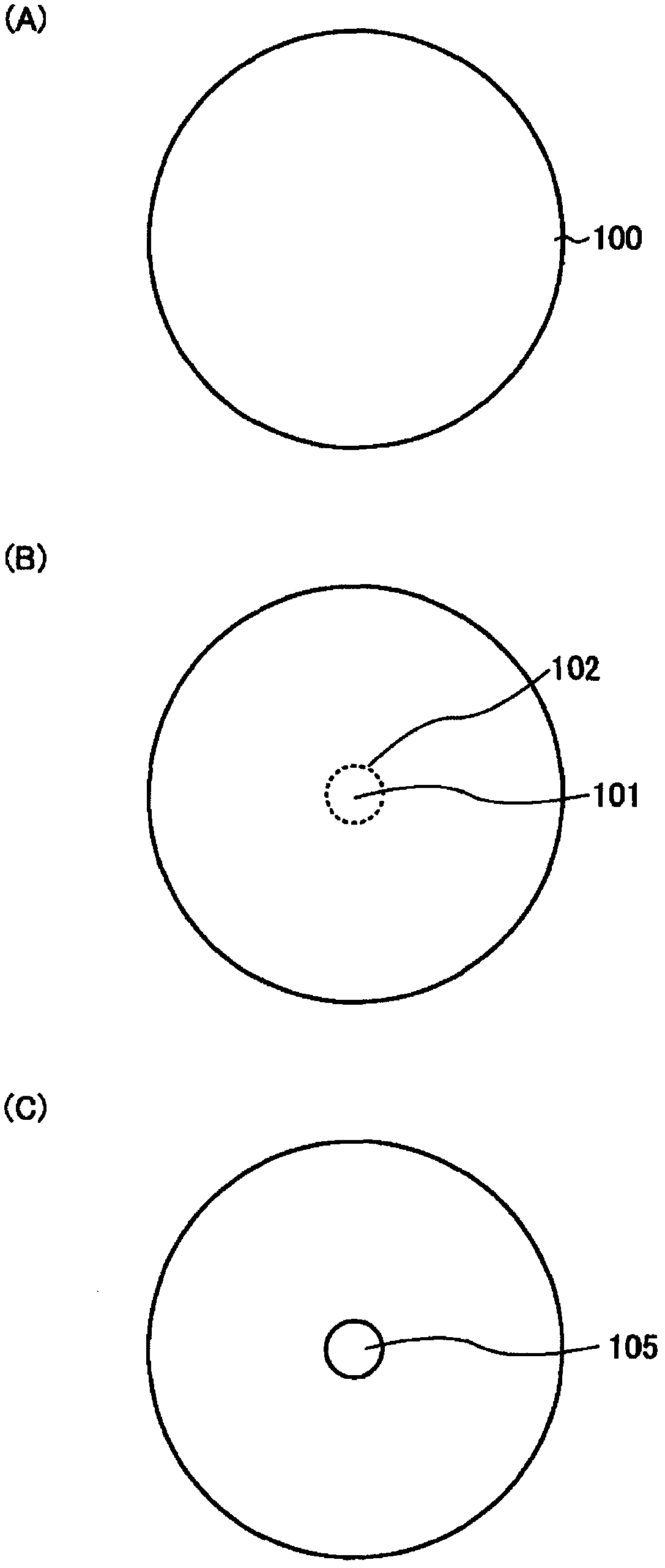
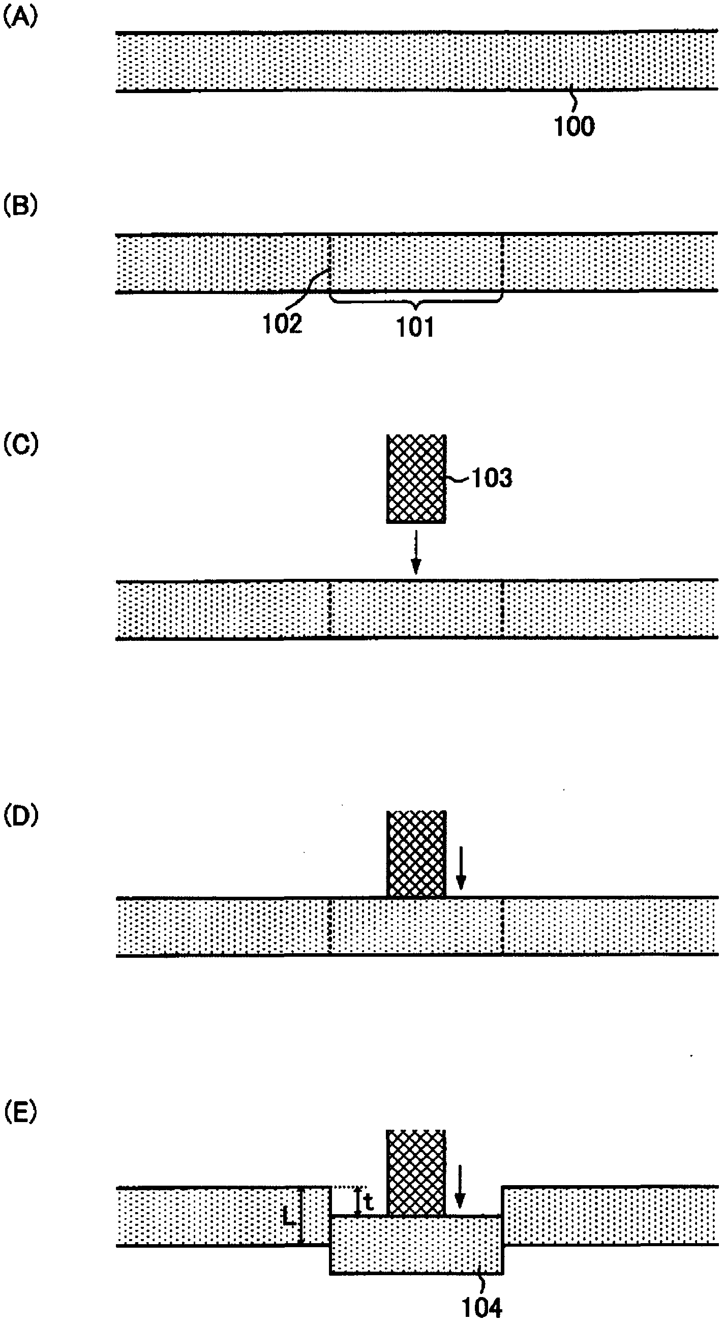
[0099] Next, the cutting line 123 constituting the periphery of the outer peripheral side of the region 122 of the glass substrate for a magnetic disk and the cutting line 125 constituting the periphery of the region 124 for forming a circular hole are formed on the bottom surface of the plate glass substrate 121 by a diamond cutter ( refer to Figure 6 (B)). Next, in the plate glass substrate, by selectively...

Embodiment 2

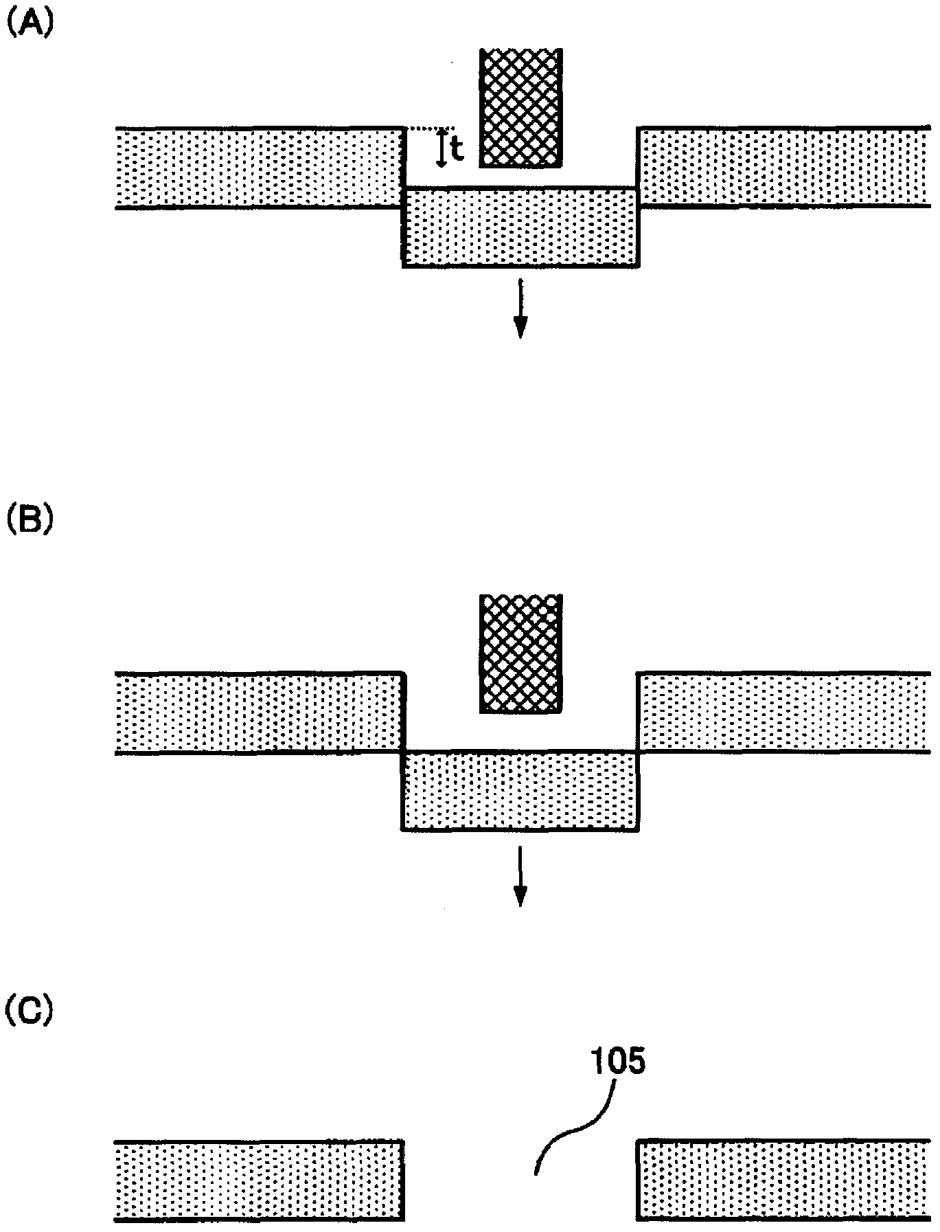
[0106] In the shape processing step, instead of heating with a heater, the top surface of the glass portion for forming the hole is selectively cooled at -20°C with a refrigerant, and an iron member with a conical tip is used as a pressing body. When the pressing body is brought into contact with the glass part to be separated from the glass substrate to be formed with a round hole from the upper side of the main surface and a force is applied downward in the vertical direction, the pressing body does not fly out from the other main surface (lower side) A glass substrate for a magnetic disk was produced in the same manner as in Example 1 except that the press body was controlled by a computer and the glass portion was separated from the glass substrate. In addition, the pressure at the point of contact with the glass part for forming a circular hole was made into about 4.0Kgf.

[0107] (defect check)

[0108] The circular hole formed on the glass substrate was inspected for t...


PUM


Abstract

Disclosed is a manufacturing method of a magnetic disk-use glass substrate having a step of forming a round hole in the glass substrate, wherein the step of forming the round hole has a first step of, for one of the main surfaces of the glass substrate, forming a cut that forms a periphery of the region that becomes the round hole in a perpendicular direction that is substantially perpendicular to that main surface of the glass substrate; a second step of causing the cut to reach the other main surface of the glass substrate; and a third step of, by causing a pushing body to come into contact and to apply force in the perpendicular direction from the side of the first-mentioned main surface toward a glass portion that is to be separated from the glass substrate in becoming the round hole, forming the round hole in the glass substrate by separating the glass portion; wherein in the third step, the glass portion is separated from the glass substrate so as not to allow the pushing body to protrude from the other main surface.

Description

technical field [0001] This invention relates to the manufacturing method of the glass substrate for magnetic discs mounted on magnetic disc devices, such as HDD (Hard Disk Drive), and a magnetic disc. Background technique [0002] With the improvement of information technology, information recording technology, especially magnetic recording technology is being remarkably advanced. In magnetic disks used for HDDs (Hard Disk Drives), which are one of magnetic recording media, rapid miniaturization, thinning, increase in recording density, and high-speed access speed are continuing. In HDD, recording and reproduction are performed while a magnetic disk having a magnetic layer is rotated at high speed on a disk-shaped substrate, and a magnetic head is floated on the magnetic disk. [0003] As the access speed is increased, the rotational speed of the magnetic disk is also increased, and therefore higher substrate strength is required for the magnetic disk. In addition, with t...

Claims


Application Information

Patent Timeline
Patent Type & Authority Applications(China)
IPC IPC(8): G11B5/84G11B5/73
CPCG11B5/8404
Inventor 崔星一
Owner HOYA CORP
Why Eureka
Try Eureka