Combined machine tool for drilling oil hole of connecting rod and cutting big-head hole of connecting rod

A combined machine tool and big head hole technology, which is applied in the direction of manufacturing tools and other manufacturing equipment/tools, can solve the problems of difficult product accuracy requirements and low processing efficiency, so as to save time and human resources, improve production efficiency, and avoid multiple The effect of secondary clamping

Active Publication Date: 2012-05-30
福建华威钜全精工科技有限公司
View PDF6 Cites 9 Cited by
  • Summary
  • Abstract
  • Description
  • Claims
  • Application Information

AI Technical Summary

Problems solved by technology

The two ends of the connecting rod are respectively provided with a big head hole and a small head hole. During the processing, the big head hole needs to be cut to form the rod body and the rod cover; and because the connecting rod needs to be continuously lubricated during the movement, it must be installed in the big head hole and the rod cover. Oil holes are drilled separately on the small head holes; in the traditional connecting rod processing process, the cutting and drilling of oil holes at the large and small ends of the connecting rod are usually divided into independent processes, and different equipment is used for processing, which requires multiple clamping to complete , the processing efficiency is low, and the product precision is difficult to meet the requirements

Method used


Image

  • Combined machine tool for drilling oil hole of connecting rod and cutting big-head hole of connecting rod
  • Combined machine tool for drilling oil hole of connecting rod and cutting big-head hole of connecting rod
  • Combined machine tool for drilling oil hole of connecting rod and cutting big-head hole of connecting rod

Examples


Embodiment Construction

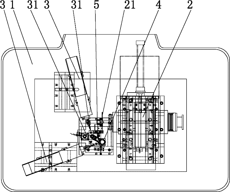
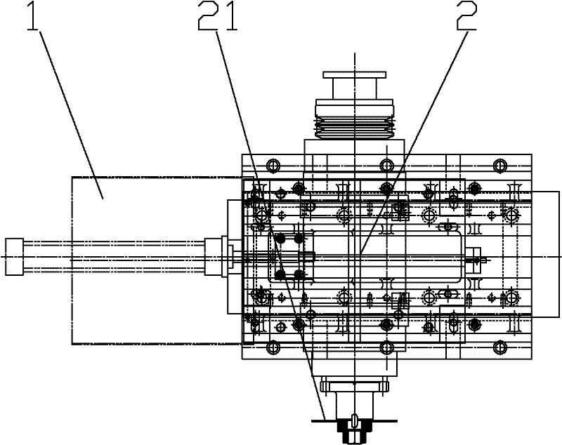
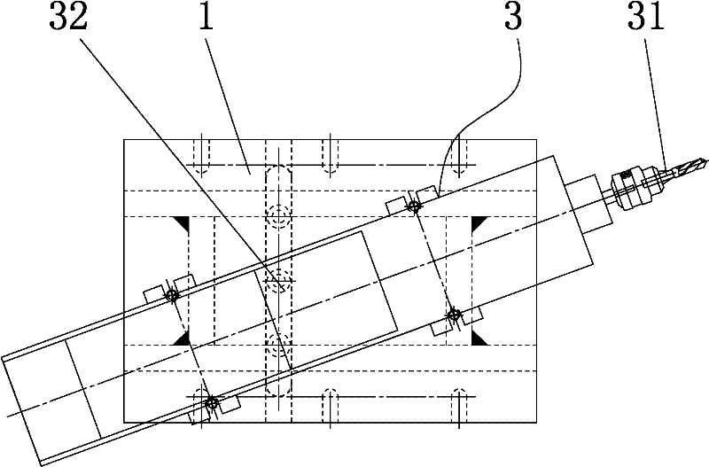
[0015] like Figures 1 to 3 As shown, the combined machine tool of the present invention includes a machine platform 1, a cutting mechanism 2, two sets of drilling mechanisms 3, and a positioning fixture 4; the positioning fixture 4 and the drilling mechanism 3 are arranged on the machine platform, and the cutting mechanism 2 and the machine platform Sliding connection, the sliding of the cutting mechanism 2 on the machine table is driven and controlled by the oil cylinder, the connecting rod 5 to be processed is fixed on the positioning fixture 4; the rotating head of the cutting mechanism 2 is fixed with a saw blade 21, and the saw blade 21 is aligned with the connecting rod 5 The cutting position of the big head hole, the cutting mechanism 2 drives the saw blade 21 to cut and move along the set cutting position of the big head hole; the drilling mechanism 3 is provided with a drill bit 31, and the drill bit 31 is pre-opened along the connecting rod 5 big head holes and small...


PUM


Abstract

The invention discloses a combined machine tool for drilling an oil hole of a connecting rod and cutting a big-head hole of the connecting rod, and the machine tool comprises a machine platform, a cutting mechanism, two sets of drilling mechanisms and a positioning fixture, wherein the positioning fixture and the drilling mechanisms are arranged on the surface of the machine platform; the cutting mechanism is in sliding connection with the surface of the machine platform; an oil cylinder is used for driving and controlling the cutting mechanism to slide on the surface of the machine platform; a to-be-processed connecting rod is fixed on the positioning fixture; a rotating head of the cutting mechanism is fixed with a saw bit; the saw bit is aligned with a cutting position of a big-head hole of the connecting rod; the cutting mechanism is used for driving the saw bit to cut and move along the preset cutting position of the big-head hole; drilling bits are arranged on the drilling mechanisms; and the drilling bits respectively do feed motion along preset oil hole drilling positions on the big-head hole and a small-head hole of the connecting rod. The invention provides a device combined with two processes of drilling the oil hole for the connecting rod and cutting the connecting rod; the operation of repeatedly clamping the connecting rod during a processing process is avoided; the relative stability of the position of the oil holes on the connecting rod is realized; the device is convenient in operation; and the production efficiency of products is increased.

Description

technical field [0001] The invention relates to the field of metal processing, in particular to a combined machine tool for drilling oil holes for processing connecting rods and cutting big holes. Background technique [0002] The connecting rod is an important part in the automobile engine. It connects the piston and the crankshaft. Its function is to convert the reciprocating motion of the piston into the rotational motion of the crankshaft, and transmit the force acting on the piston to the crankshaft to output power. The two ends of the connecting rod are respectively provided with a big head hole and a small head hole. During the processing, the big head hole needs to be cut to form the rod body and the rod cover; and because the connecting rod needs to be continuously lubricated during the movement, it must be installed in the big head hole and the rod cover. Oil holes are drilled separately on the small head holes; in the traditional connecting rod processing process,...

Claims


Application Information

Patent Timeline
Patent Type & Authority Applications(China)
IPC IPC(8): B23P23/02
Inventor 薛玉田
Owner 福建华威钜全精工科技有限公司
Why Eureka
Try Eureka