High-power inverter system

An inverter and high-power technology, applied in the field of high-power inverter systems, can solve problems such as system complexity, achieve the effects of reducing costs, improving system reliability, and simplifying software and hardware control circuits

Inactive Publication Date: 2012-05-30
ZTE CORP
View PDF5 Cites 10 Cited by
  • Summary
  • Abstract
  • Description
  • Claims
  • Application Information

AI Technical Summary

Problems solved by technology

[0006] In order to solve the circulating current problem in the related art, it is necessary to add additional hardware circuits and software control logic to make the system complicated, etc., the present invention provides a high-power inverter system to solve at least one of the above-mentioned problems

Method used


Image

  • High-power inverter system
  • High-power inverter system
  • High-power inverter system

Examples


example 1

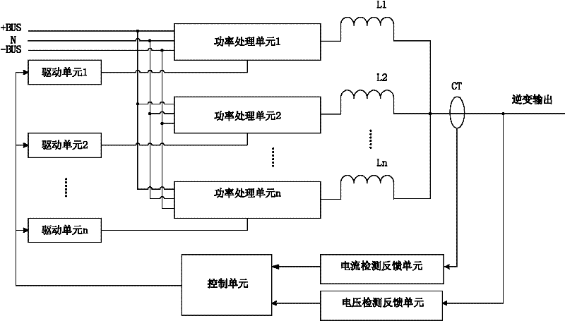
[0034] Figure 4 It is a schematic structural diagram of a high-power inverter system according to Example 1 of the present invention. Such as Figure 4 As shown, the above-mentioned high-power inverter system is a two-branch parallel three-phase inverter system composed of IGBT as the main power device. The system mainly includes: 6 half-bridge arms, high-voltage DC bus, output filter inductor, output filter capacitor, drive circuit, DSP control unit, three-phase current detection feedback unit and three-phase voltage detection feedback unit.

[0035] Among them, each inverter parallel branch (equivalent to the above-mentioned power processing unit) adopts a half-bridge topology, the midpoint of each bridge arm is connected to its own output filter inductor, and each two branches are directly connected in parallel after the output filter inductor as a Phase output; 6 bridge arms are connected in parallel to realize three-phase output.

[0036] After the output filter induc...

example 2

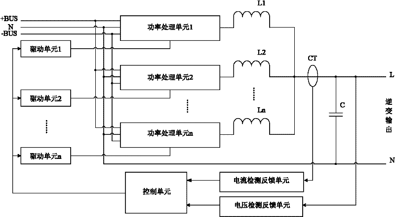
[0039] Figure 5It is a schematic structural diagram of a high-power inverter system according to Example 2 of the present invention. Such as Figure 5 As shown, the above-mentioned high-power inverter system is a three-branch parallel single-phase high-power inverter system composed of power MOSFETs and fast recovery diodes. The system mainly includes: 3 inverter parallel branches and peripheral high-voltage DC input unit, DSP control unit, drive unit, sampling unit, and LC filter unit.

[0040] Among them, each inverter parallel branch (equivalent to the above-mentioned power processing unit) is a diode-clamped three-level inverter circuit. Taking branch 1 as an example, it includes four internal inverters connected in series between the positive and negative bus bars. Power MOS transistors VT1, VT2, VT3, VT4 of parallel diodes; and clamping diodes VD1, VD2 connected between the MOS transistors and the neutral point. The MOS tube and the clamping diode can be in the form ...


PUM


Abstract

The invention discloses a high-power inverter system, which comprises a plurality of branch circuits in parallel connection. Each branch circuit comprises a power processing unit, output filter inductors, a current transformer, a current detecting feedback unit, a voltage detecting feedback unit, a control unit and one or a plurality of driving units, wherein the power processing unit and the output filter inductors are in serial connection, an input end of the current transformer is connected with connection nodes of each output filter inductor, an input end of the current detecting feedback unit is connected with an output end of the current transformer, an input end of the voltage detecting feedback unit is connected with an output end of the high-power inverter system, one input end of the control unit is connected to an output end of the current detecting feedback unit, and another input end of the control unit is connected to an output end of the voltage detecting feedback unit, and the driving units are connected between an output end of the control unit and a driving port of each power processing unit and used for driving the power processing units. According to the technical scheme, software and hardware control circuits can be simplified, and cost is reduced while reliability of the system is improved.

Description

technical field [0001] The invention relates to the field of power supplies, in particular to a high-power inverter system. Background technique [0002] With the increasing demand of electronic equipment on the power level of the power system, in order to achieve high power output, a modular system in which multiple low-power single units are connected in parallel or multiple low-power modules are connected in parallel is generally used until the power demand of the load is met. [0003] figure 1 It is a block diagram of an inverter system in which multiple power monomers (single machines or modules) are connected in parallel in the related art. Such as figure 1 As shown, the system includes: n power cells connected in parallel. The above inverter system can improve the power level of the entire power supply system, and can form n+x redundancy, which improves the stability of the power supply system. However, the parallel connection of multiple monomers not only increas...

Claims


Application Information

Patent Timeline
Patent Type & Authority Applications(China)
IPC IPC(8): H02M7/539
Inventor 王海林
Owner ZTE CORP
Why Eureka
Try Eureka