
Control device for internal combustion engine

A technology for control devices and internal combustion engines, which is applied in engine control, fuel injection devices, fuel injection control, etc., and can solve problems such as catalyst temperature rise and catalyst degradation

Inactive Publication Date: 2012-05-30
TOYOTA JIDOSHA KK
View PDF9 Cites 4 Cited by
  • Summary
  • Abstract
  • Description
  • Claims
  • Application Information

AI Technical Summary

Problems solved by technology

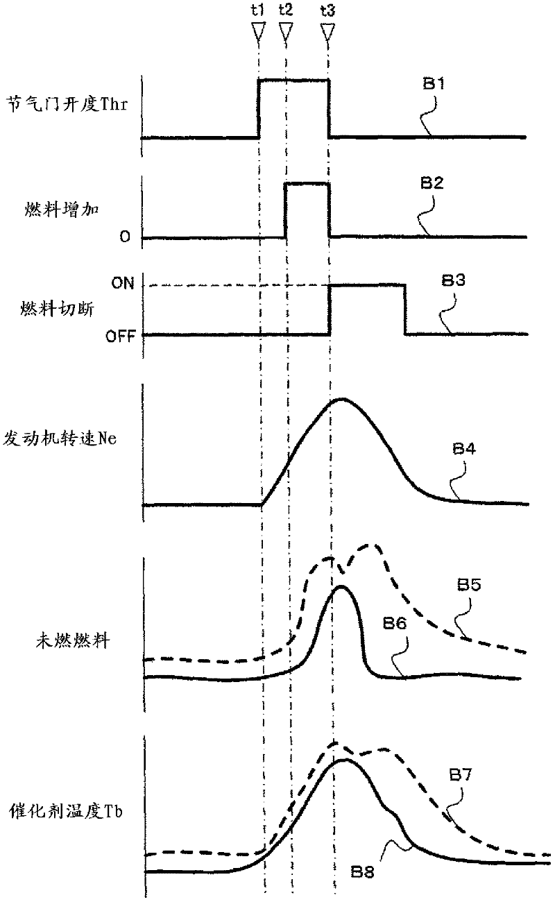
Therefore, when the fuel cut is performed with deceleration thereafter, the above-mentioned unburned fuel flows into the exhaust system, and since the unburned fuel and a large amount of oxygen promote the oxidation reaction in the catalyst, there is a possibility that the temperature of the catalyst is raised and the catalyst is further deteriorated.

Method used


Image

  • Control device for internal combustion engine
  • Control device for internal combustion engine
  • Control device for internal combustion engine

Examples


Embodiment Construction

[0016] Hereinafter, preferred embodiments of the present invention will be described with reference to the accompanying drawings.

[0017] Schematic composition of an internal combustion engine

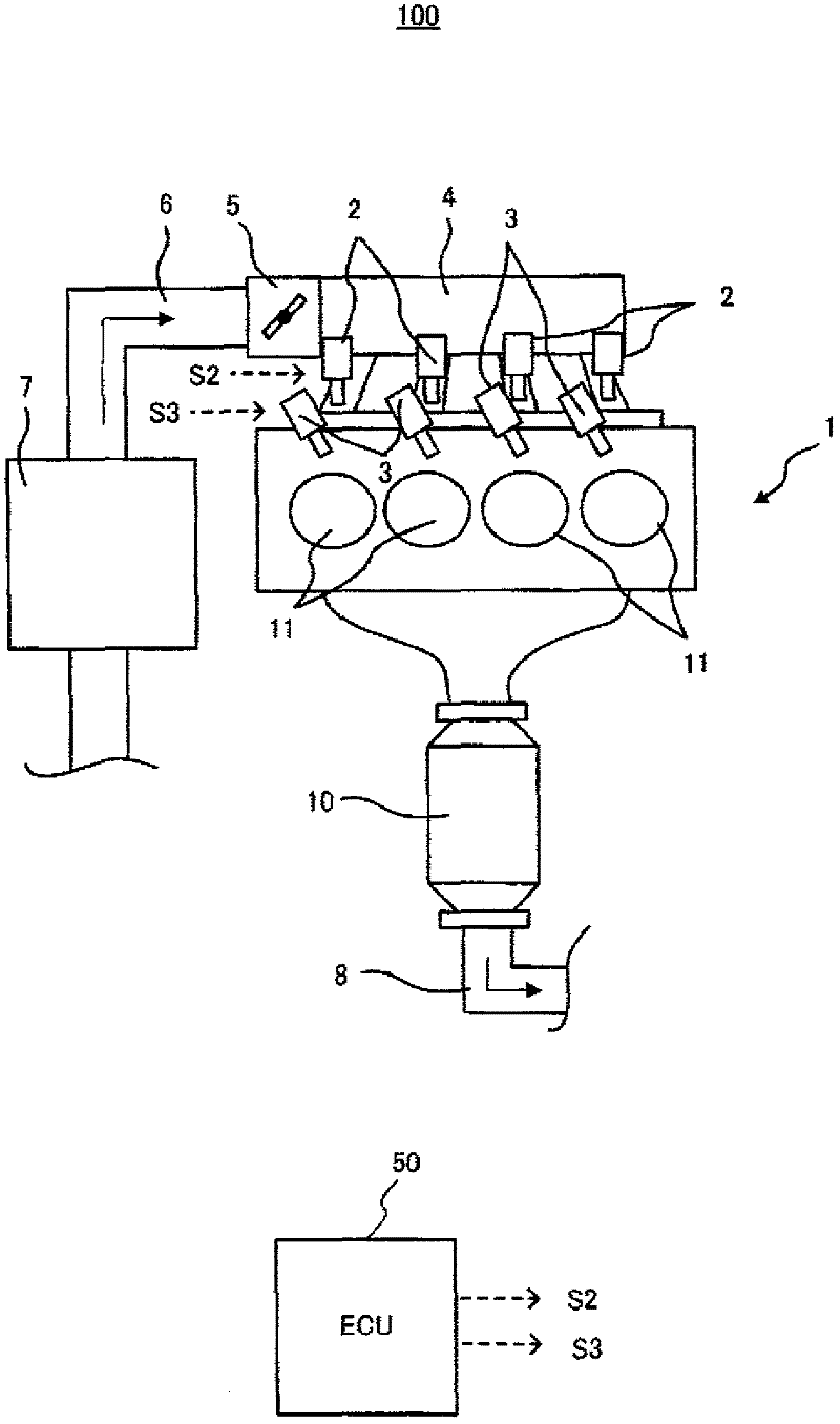
[0018] figure 1 A fuel injection system 100 to which the internal combustion engine control device of the present invention is applied is shown. The solid-line arrows in the figure represent an example of the flow of the gas.

[0019] The fuel injection system 100 mainly includes an engine 1, a first fuel injection valve 2, a second fuel injection valve 3, a surge tank 4, a throttle valve 5, an intake passage 6, an air cleaner 7, an exhaust passage 8, and a catalyst 10.

[0020] The engine 1 includes four cylinders 11, and each of the cylinders 11 is connected to a common surge tank 4 via an intake manifold. Furthermore, each cylinder 11 is provided with a first fuel injection valve 2 for injecting gas fuel and a second fuel injection valve 3 for injecting liquid fuel, respectivel...


PUM


Abstract

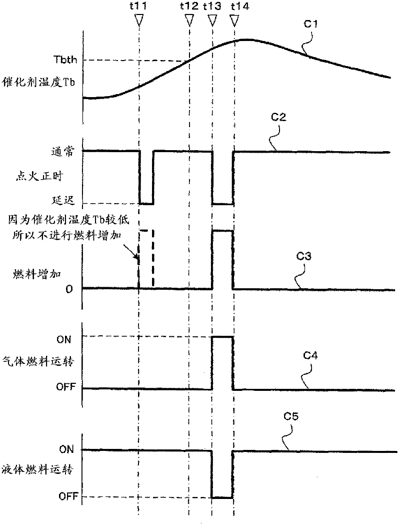
A control device for an internal combustion engine is installed in a vehicle and is provided with an engine, a catalyst, and a control means. The engine is a bi-fuel engine operating on both gaseous fuel and liquid fuel. If the temperature of the catalyst exceeds a predetermined upper limit value when the liquid fuel is being used, the control means enriches the air-fuel ratio and increases the proportion of the gaseous fuel.

Description

technical field [0001] The present invention relates to vehicle control including an internal combustion engine (engine). Background technique [0002] Conventionally, there has been known a technique for reducing the exhaust gas temperature by increasing the fuel injection amount when the catalyst becomes high temperature. For example, Patent Document 1 discloses a technique for increasing the ethanol fuel ratio when the temperature of the catalyst is raised to the upper limit temperature or higher for fuel containing ethanol. In this case, since the heat of evaporation and the combustion temperature are different, the catalyst temperature is reduced and the catalyst deterioration is suppressed. In addition, Patent Document 2 discloses a technique of changing the setting of the temperature at which the fuel cut is performed based on the oxygen-containing fuel ratio of the fuel in order to prevent the temperature of the exhaust system from rising excessively. [0003] Pate...

Claims


Application Information

Patent Timeline
IPC IPC(8): F01N3/24F02D19/06F02D41/02
CPCF02D19/0692F02D41/0027F02D19/0615F02D19/061F02D2200/0802Y02T10/36F02M43/04F02D41/0235F02D2041/0265F02D19/081F02D19/0647F02D41/0025F02D41/1446Y02T10/30
Inventor 星幸一渡边刚篠田祥尚
Owner TOYOTA JIDOSHA KK
Learn More