Catalytic cracking method and device thereof

A catalytic cracking device and catalytic cracking technology, which is applied in the fields of refining and cracking process treatment, petroleum industry, hydrocarbon oil treatment, etc., can solve the problems of difficulty in significantly improving catalyst performance, difficulty in termination control, and impact on economy, etc. , to achieve the effect of enhancing catalytic reaction selectivity, ensuring reactivity, and making simple

Inactive Publication Date: 2014-03-05
石宝珍
View PDF5 Cites 0 Cited by
  • Summary
  • Abstract
  • Description
  • Claims
  • Application Information

AI Technical Summary

Problems solved by technology

[0004] However, DCC technology has the following problems that need to be improved in engineering implementation: A. The spent agent in the riser part all enters the bed layer reaction zone, and it is difficult to significantly improve the performance of the catalyst in this zone; B. The termination control of the reaction is difficult; especially After increasing the temperature of the bed reaction zone, there will be more gas products and a higher coke yield. Only the side reaction caused by the settler will increase the dry gas by 2 percentage points, which will affect the economy.

Method used


Image

  • Catalytic cracking method and device thereof
  • Catalytic cracking method and device thereof
  • Catalytic cracking method and device thereof

Examples


Embodiment 1

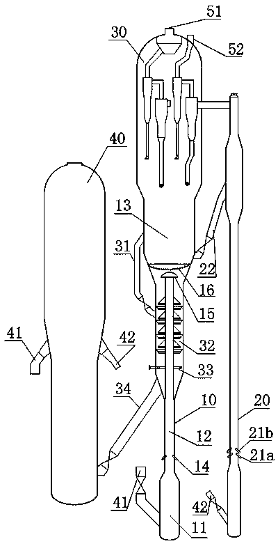
[0046] The design of a catalytic cracking unit in an oil refinery is as follows: figure 1 As shown, the first reaction zone 12 of the main reactor has a diameter of 1.4m, and the second reaction zone 13 has a bed diameter of 7.2m; the secondary reactor 20 is a riser reactor with a diameter of 0.9m; the catalyst return pipe 31 adopts an external circulation pipe; , Secondary reactor oil gas is drawn respectively by oil gas outlet 51,52 and handles separately; Reaction process is as follows:

[0047] The heavy oil preheated at 220°C is atomized through the nozzle 14, enters the riser of the first reaction zone 11 of the main reactor 10, and is mixed with the regenerated catalyst to gasify, then flows upwards along the first reaction zone 11, and reacts continuously, the reaction temperature 520°C, reaction time 1.0s, after the reaction is completed, the mixture is separated from the catalyst through the splitter 15, and the oil and gas enter the fluidized bed of the second reac...

Embodiment 2

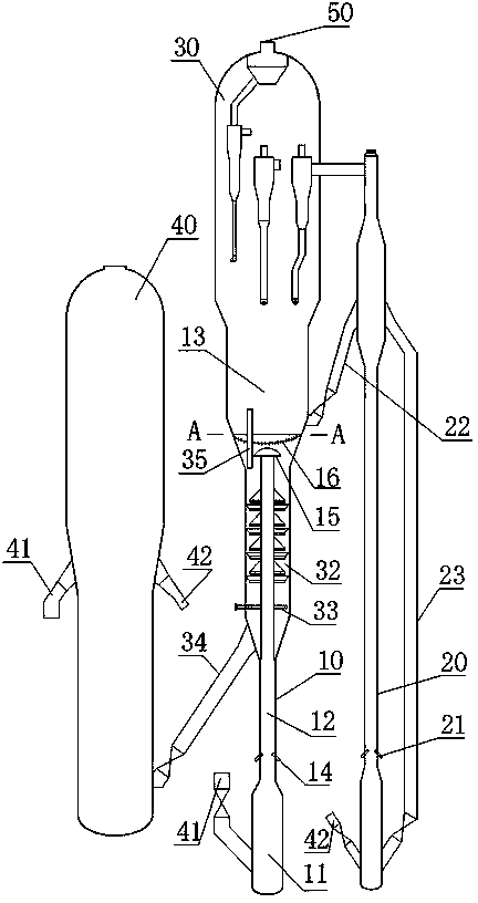
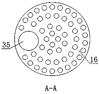
[0050] Such as figure 2 As shown, the catalyst return pipe 35 adopts the form of an inner overflow pipe; the catalyst return pipe 23 is arranged between the middle part and the bottom of the secondary reactor 20; the main and secondary reactors are mixed with oil and gas, and are drawn out from the common outlet 50; the rest of the device structure is the same as figure 1 . During the reaction process of the secondary reactor 20, 20% spent catalyst is introduced into the bottom of the reactor 20 through the catalyst return pipe 22, so as to reduce the thermal cracking process of the secondary reactor. In this embodiment, the specific device A-A direction structure of the inner overflow pipe 35 passing through the distribution plate 16 is as follows image 3 shown.

Embodiment 3

[0052] Such as Figure 4 As shown, the outlet of the lower material leg 37 of the front-stage gas-solid cyclone of the two-stage gas-solid cyclone of the secondary reactor 20 directly extends into the fluidized bed of the second reaction zone 13, thereby introducing into the second reaction zone Standing catalyst. The rest of the device structure is the same as figure 1 .


PUM


Abstract

The invention which discloses a catalytic cracking method and a device thereof belongs to the technical field of the petrochemical industry. A catalytic cracking reaction is carried out in a primary reactor and a secondary reactor, a regenerated catalyst from a regenerator contacts and reacts with raw oil in a first reaction zone of the primary reactor, and the obtained reaction mixture which upward goes through a splitter is separated to obtain a catalyst; the separated catalyst directly flows to a stripping stage, and a reaction oil gas which goes through a distribution plate upward enters a fluidized bed in a second reaction zone of the primary reactor; and a catalyst to be regenerated or a mixture of the catalyst to be regenerated and a reaction oil gas in the secondary reactor, which enters the second reaction zone of the primary rector, is mixed with the reaction oil gas from the first reaction zone to continuously react the reaction oil gas. According to the invention, the catalyst displacement in the second reaction zone is realized, so the catalytic selectivity of the primary reactor is reinforced; the rapid termination control of the primary reactor is adopted to reduce the generation of a side reaction; and the device with a connected design and a common stripping stage is adopted to reduce the investment.

Description

technical field [0001] The invention relates to the technical field of petrochemical industry, in particular to a catalytic cracking method and device. Background technique [0002] Propylene is one of the most basic raw materials in the chemical industry. The existing catalytic conversion technology only produces low-carbon olefins such as propylene by-products while producing gasoline and diesel, which is far from meeting the current market demand for propylene. At home and abroad, natural gas or light petroleum fractions are mostly used as raw materials, and low-carbon olefins are produced by the steam cracking process in ethylene complexes. The amount of olefins produced by cracking ethane and other low-carbon alkanes in the world is about 136 million tons every year; this This cracking process for producing olefins requires high energy consumption and heavy pollution. According to relevant statistics, nitrogen oxides and unburned hydrocarbon emissions produced by this ...

Claims


Application Information

Patent Timeline
Patent Type & Authority Patents(China)
IPC IPC(8): C10G55/06C10G51/00
Inventor 石宝珍
Owner 石宝珍
Why Eureka
Try Eureka