Catalytic cracking method and apparatus
A catalytic cracking device and catalytic cracking technology, which are applied in the fields of refining and cracking process treatment, petroleum industry, and hydrocarbon oil treatment in multi-stage series, can solve the problems of affecting the stripping effect, affecting the regeneration process, and increasing investment. Reduce unfavorable secondary reactions, reduce olefin content, and simplify the production of equipment
- Summary
- Abstract
- Description
- Claims
- Application Information
AI Technical Summary
Problems solved by technology
Method used
Image
Examples
Embodiment 1
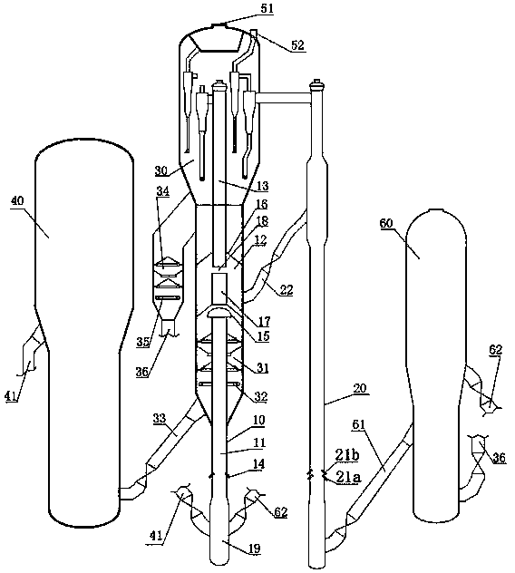
[0039] In the method of the present invention, the reaction raw materials in the secondary reactor and the second reaction zone of the main reactor (i.e. the light raw material in the secondary reactor and the oil and gas after the reaction in the first reaction zone) are lighter than the reaction raw materials in the first reaction zone, The S content is low, during the reaction process, there is no metal pollution to the catalyst, and the coke formation is low, so the second regenerator can adopt different regeneration conditions from the first regenerator, and there is no need to replace the catalyst; in addition, the regeneration temperature is lowered It can also reduce NO in regeneration flue gas X The formation is conducive to environmental protection.
[0040] figure 1 It is a schematic diagram of a catalytic cracking unit in an oil refinery, the first regenerator 40 is regenerated at 680-700°C, and the second regenerator 60 is regenerated at 620-650°C; the reaction ...
Embodiment 2
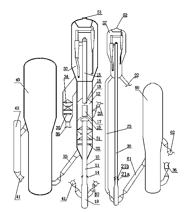
[0046] The design of a catalytic cracking unit in an oil refinery is as follows: figure 2 As shown, a catalyst cooler 43 is set on the regeneration standpipe 41, a second settler 37 is set in the secondary reactor 20, a catalyst return pipe 23 is arranged between the second settler 37 and the bottom of the secondary reactor 20, and the second settler There is a catalyst relay pipe 22 between 37 and the catalyst replenishment area 12; the oil and gas in the two reactors are treated separately. The rest of the device structure is the same as figure 1 . In the present embodiment, the circulation rate of the spent catalyst that is refluxed from the reactor 20 is controlled by the slide valve on the catalyst return pipe 23, and the reflux rate is 40%; the reaction raw material of the reactor 20 is mixed C 4 components. In this embodiment, the reaction temperature in the first reaction zone of the reactor 10 is 500°C, and the reaction time is 1.0s; the reaction temperature in t...
PUM
| Property | Measurement | Unit |
|---|---|---|
| boiling point | aaaaa | aaaaa |
Abstract
Description
Claims
Application Information
 - R&D
- Intellectual Property
- Life Sciences
- Materials
- Tech Scout
- Unparalleled Data Quality
- Higher Quality Content
- 60% Fewer Hallucinations
Browse by: Latest US Patents, China's latest patents, Technical Efficacy Thesaurus, Application Domain, Technology Topic, Popular Technical Reports.
© 2025 PatSnap. All rights reserved.Legal|Privacy policy|Modern Slavery Act Transparency Statement|Sitemap|About US| Contact US: help@patsnap.com


