Continuous multi-shaft cement mixing pile device and construction method

A technology of mixing piles and cement-soil, which is applied in earthwork drilling, drilling equipment and methods, excavation, etc., which can solve the problems of insufficient starting power, poor stability, and high labor intensity, and achieve the reduction of lap joint cold joints and the rotation load Good effect of lightening and safety performance

Inactive Publication Date: 2012-06-13
SHANGHAI CHENGDI CONSTR
View PDF5 Cites 21 Cited by
  • Summary
  • Abstract
  • Description
  • Claims
  • Application Information

AI Technical Summary

Problems solved by technology

[0003] The two-axis mixing pile is a construction method extended in the 1980s. The frame is a well-shaped frame, which walks in a tube, has extremely poor stability, low work efficiency, and high labor intensity. In addition, the power head part uses a 37kw conventional motor, and the starting power is insufficient.
The deepest pile is only 18m long, and the lower drill pipe has only two blades, so the mixing is not uniform, and the quality of the lower pile is difficult to guarantee. Each pile is 1.2 meters long, resulting in many overlapping cold joints, which is easy to cause water leakage and other phenomena
[0004] The disadvantage of the SMW construction method is that

Method used


Image

  • Continuous multi-shaft cement mixing pile device and construction method
  • Continuous multi-shaft cement mixing pile device and construction method
  • Continuous multi-shaft cement mixing pile device and construction method

Examples


Embodiment 1

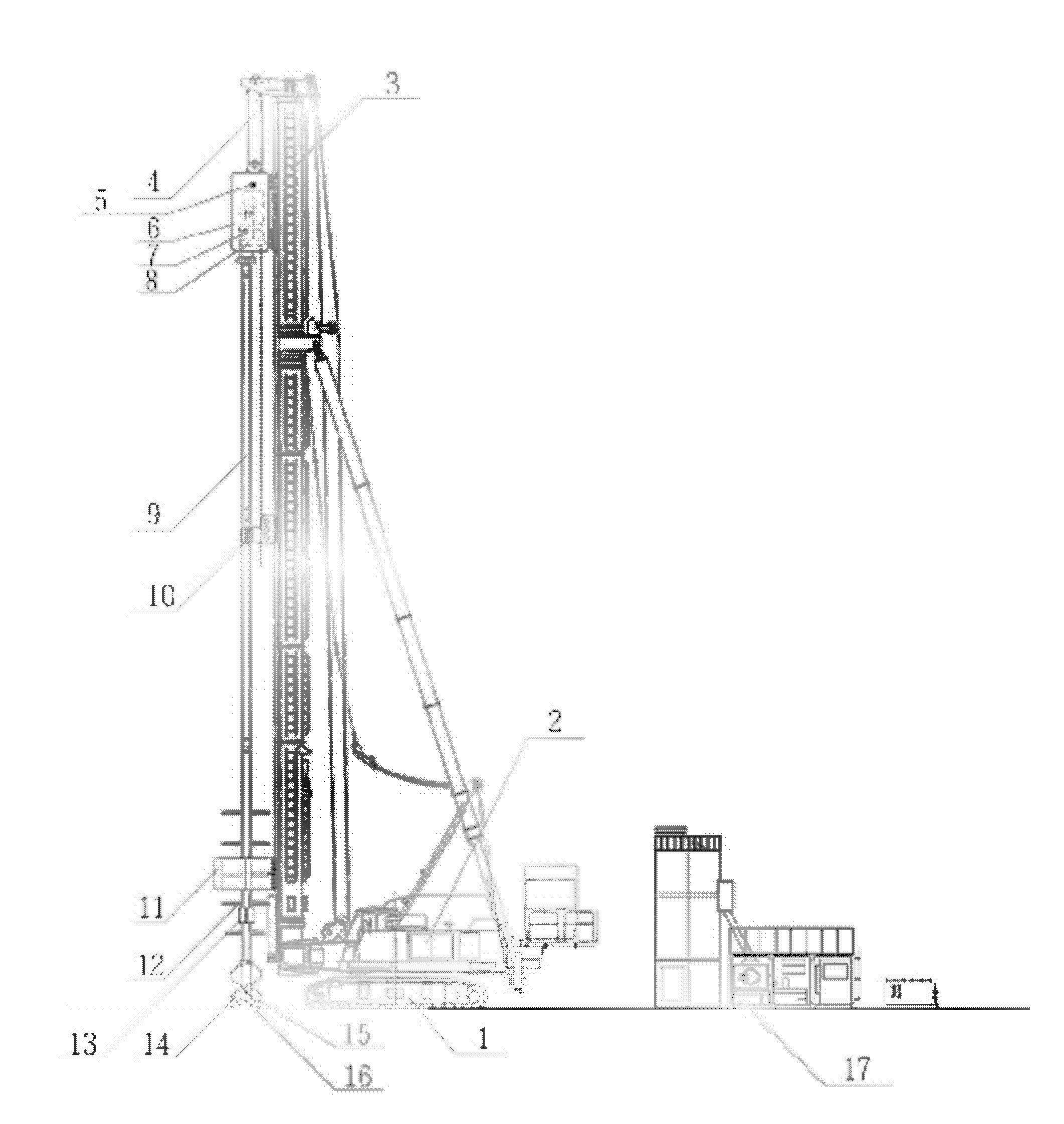
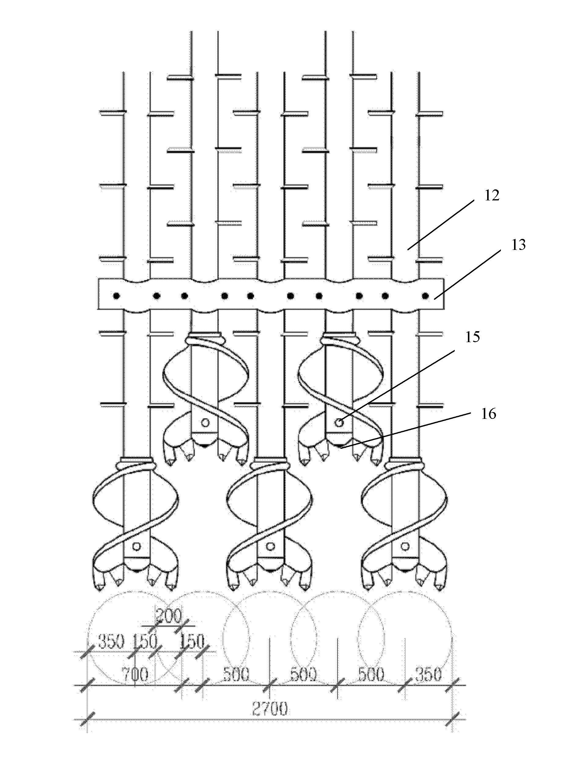
[0033] Such as Figure 1~2 As shown, a multi-axis cement-soil continuous mixing pile device includes a crawler-type and walking-type main engine 1, a winch 2, a guide rod 3, a steel wire rope 4, an air inlet for slurry 5, a power head 6, a gearbox 7, Reducer 8, drill pipe 9, intermediate support frame 10, lower support frame 11, winged drill pipe 12, hoop 13, drill bit 14, air injection port 15, spray port 16, the hoist 2 and guide rod 3 are fixed On the host machine 1, the power head 6 is connected to the top pulley of the guide rod 3 through the wire rope 4, and the wire rope 4 drives the power head 6 to go up and down, and the power head 6 is connected to five drill pipes through the gearbox 7 and the reducer 8 in turn. 9. The middle part of the five drill pipes 9 is provided with an intermediate support frame 10, and the lower part is provided with a lower support frame 11. The lower ends of each drill pipe 9 are connected with winged drill pipes 12, and the winged drill p...

Embodiment 2

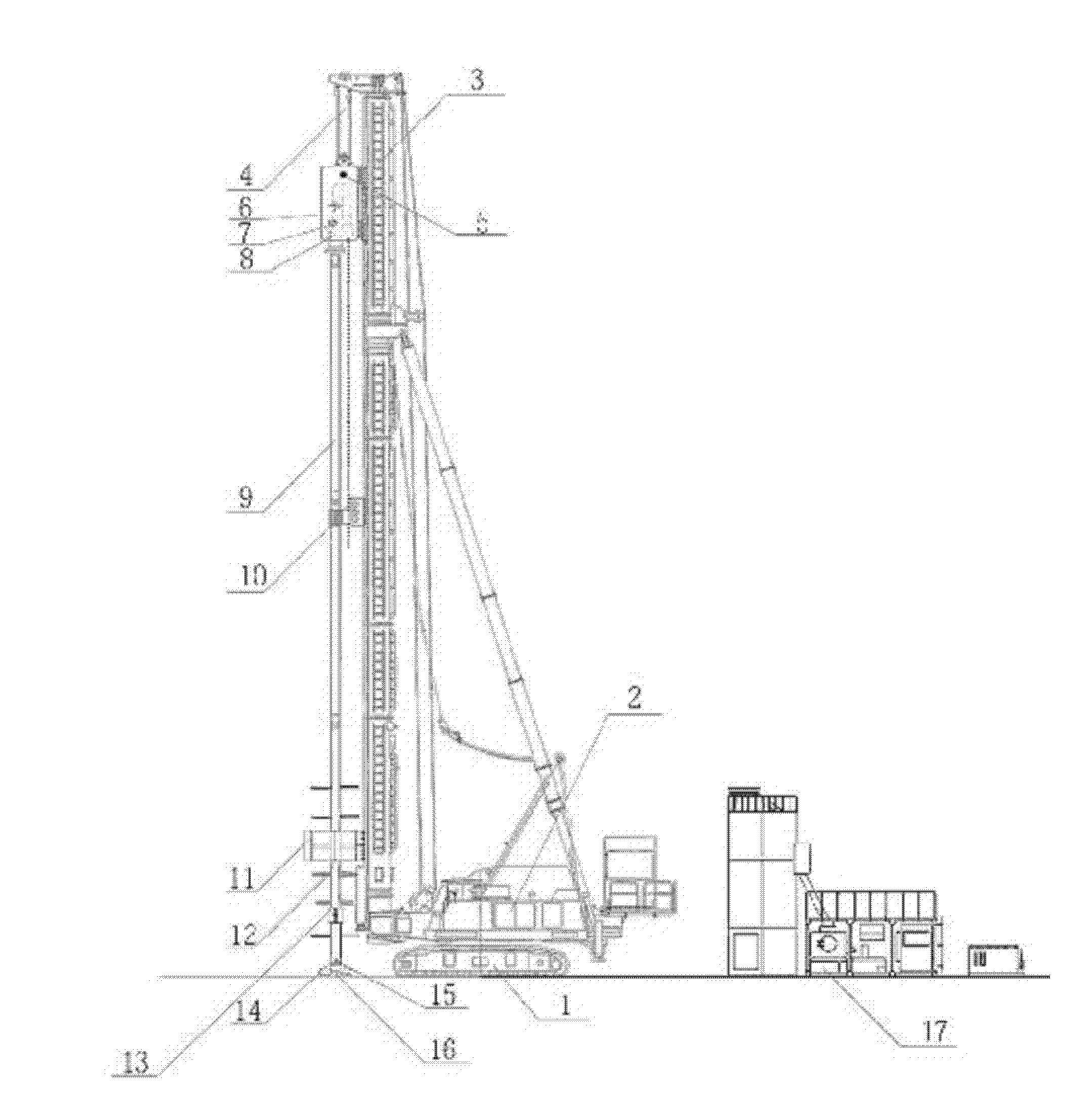
[0049] Such as Figure 3-4 As shown, a multi-axis cement-soil continuous mixing pile device, the drill bit 13 is a rake drill bit. All the other are with embodiment 1.

[0050] Described drilling rod can be set 3-7 as required.


PUM


Abstract

The invention relates to a continuous multi-shaft cement mixing pile device and a construction method; the multi-shaft continuous cement mixing pile device comprises a walking type main machine, a crawler type main machine, a winding engine, a guide rod, a steel wire rope, an air and grout inlet, a power head, a speed changing box, a reduction box, drill stems, middle supporting frames, lower supporting frames, winged drill stems, hoops, drill bits, air injection ports, grout spraying ports and a background cement grout stirring system, wherein the winding engine and the guide rod are fixed on the main machines, the power head is connected with a pulley arranged at the top end of the guide rod through the steel wire rope; the steel wire rope drives the power head to be lifted up and down; the power head is sequentially connected with the multiple drill stems through the speed changing box and the speed reducer; the middle supporting frames are arranged in the middle parts of the multiple drill stems; the lower supporting frames are arranged at the lower parts of the multiple drill stems; the winged drill stems are connected with the lower ends of the drill stems; the hoops are arranged on the winged drill stems; the drill bits are connected with the lower end of the winged drill stems; and the air injection ports and the grout spraying ports are arranged on the drill bits. Compared with the prior art, the continuous multi-shaft cement mixing pile device has the advantages of noiselessness, non vibration, ensured safety and quality, cost reduction, high efficiency, shortened construction period and the like.

Description

technical field [0001] The invention relates to a multi-axis cement-soil continuous mixing pile device and a construction method, which are mainly used in foundation pit enclosure, water stop and foundation reinforcement in civil and industrial infrastructure construction. Background technique [0002] At present, two-axis mixing piles and SMW construction methods are mostly used for foundation pit enclosure and foundation reinforcement. [0003] The two-axis mixing pile is a construction method extended in the 1980s. The frame is a well-shaped frame, which walks in a tube, has extremely poor stability, low work efficiency, and high labor intensity. In addition, the power head part uses a 37kw conventional motor, and the starting power is insufficient. . The deepest pile is only 18m long, and the lower part of the drill pipe has only two blades. The mixing is not uniform, and the quality of the lower part of the pile is difficult to guarantee. Each pile is 1.2 meters long, ...

Claims


Application Information

Patent Timeline
IPC IPC(8): E02D5/46E21B7/02E21B17/22E02D5/20E02D19/18E02D17/02
Inventor 黄立伟谢曙东谢益飞卢静民鲍国强
Owner SHANGHAI CHENGDI CONSTR
Why Eureka
Try Eureka