Readout circuit bias structure

A technology of bias structure and readout circuit, applied in electrical components, electrical radiation detectors, electrical signal transmission systems, etc. Effect

Active Publication Date: 2012-06-13
UNIV OF ELECTRONICS SCI & TECH OF CHINA
View PDF5 Cites 20 Cited by
  • Summary
  • Abstract
  • Description
  • Claims
  • Application Information

AI Technical Summary

Problems solved by technology

Finally, the signal output changes with the substrate

Method used


Image

  • Readout circuit bias structure
  • Readout circuit bias structure
  • Readout circuit bias structure

Examples


Embodiment Construction

[0022] The present invention will be further described below in conjunction with accompanying drawing and embodiment:

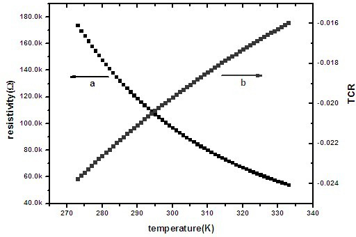
[0023] Such as figure 1 As shown, the resistance value and TCR (temperature coefficient of resistance) of the resistance type bolometer vary with the temperature of the substrate. Among them, the curve a represents the resistance value, and the curve b represents the TCR. The effect of TCR and resistance changes with the substrate temperature.

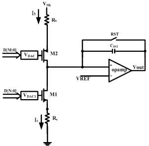
[0024] For existing readout circuit bias structures such as figure 2 As shown, when the substrate temperature changes, the reference resistance R b and the resistance of the thermistor Rs have changed. When there is infrared radiation, the signal current also changes at different substrate temperatures, as shown in formula (1):

[0025]

[0026] in V b is the reference resistor R b the bias voltage, V s for thermal R s on the bias voltage.

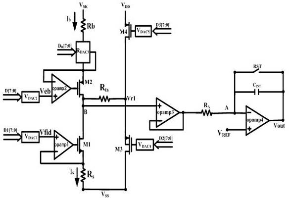
[0027] A read circuit bias structure without TEC of the present...


PUM


Abstract

The invention discloses a readout circuit bias structure, which comprises a first MOS (metal oxide semiconductor) transistor, a second MOS (metal oxide semiconductor) transistor, a reference resistor, a thermistor, operational amplifiers, a temperature compensation resistor, a third MOS (metal oxide semiconductor) transistor and a fourth MOS (metal oxide semiconductor) transistor, wherein one endof the temperature compensation resistor is connected between the first MOS transistor and the second MOS transistor, the other end of the temperature compensation resistor is connected between the third MOS transistor and the fourth MOS transistor and connected with a substrate of the third MOS transistor, an in-phase input end of the third operational amplifier is connected between the first MOS transistor and the second MOS transistor, and an anti-phase input end of the third operational amplifier is connected with an output end of the third operational amplifier to form a unity-gain buffer. Besides, the unity-gain buffer is connected to an inverted input end of the fourth operational amplifier through the resistor, and an integrating capacitor is used for integration and voltage output.

Description

technical field [0001] The invention relates to the technical field of infrared focal plane readout circuits, in particular to a readout circuit bias structure without a TEC (semiconductor cooler). Background technique [0002] All objects emit thermal radiation related to their temperature and material properties. The thermal radiation of objects near the ambient temperature is mostly in the infrared band, with a wavelength of about 1 μm to 24 μm. Infrared radiation provides a wealth of information in the objective world. It is the goal that people pursue to convert invisible infrared radiation into measurable signals and make full use of this information. Infrared focal plane array is an important optoelectronic device to obtain the infrared radiation information of the scene. Infrared focal plane detectors have been developed rapidly since 1973 when the US Air Force Development Center first proposed the silicide Schottky barrier detector array for infrared thermal imagin...

Claims


Application Information

Patent Timeline
IPC IPC(8): G01J5/10H03M1/50
Inventor 吕坚周云蒋亚东王璐霞阙隆成
Owner UNIV OF ELECTRONICS SCI & TECH OF CHINA
Why Eureka
Try Eureka