Direct-injection type flame detector with self-checking light source and flame detection method

A flame detector and light source technology, applied in photometry, photometry using electric radiation detectors, optical radiation measurement, etc., can solve the problems of poor consistency and repeatability, inability to realize real-time monitoring, low detection efficiency, etc. problems, to achieve the effect of improving the ability to resist false alarms, improving environmental adaptability, and improving reliability

Active Publication Date: 2012-06-13
SHENYANG FIRE RES INST OF MEM
View PDF5 Cites 17 Cited by
  • Summary
  • Abstract
  • Description
  • Claims
  • Application Information

AI Technical Summary

Problems solved by technology

Although there are already some formed artificial light sources used for on-site detection of flame detectors, hand-held on-site detection equipment has also solved the problem of poor consistency and repeatability of previous on-site ignition test devices, but this type of detection equipment is still limited by installation position, and real-time monitoring cannot be realized. Some manufacturers have developed the principle of light reflection. By setting a self-test light source inside the detector, the light of the detection light source will be reflected through the reflector outside the detection window, and the reflected light will pass through the protection. The lens is incident on the sensor again to realize self-test
This design basically realizes the self-inspection function, but the entire optical path uses two protective lenses and one reflector, the detection efficiency is low, and the probability of contamination is high, so it is necessary to study the flame detector using a simple self-inspection optical path to realize Its good optical integrity

Method used


Image

  • Direct-injection type flame detector with self-checking light source and flame detection method
  • Direct-injection type flame detector with self-checking light source and flame detection method
  • Direct-injection type flame detector with self-checking light source and flame detection method

Examples


Embodiment Construction

[0058] The present invention will be further described below in conjunction with accompanying drawing.

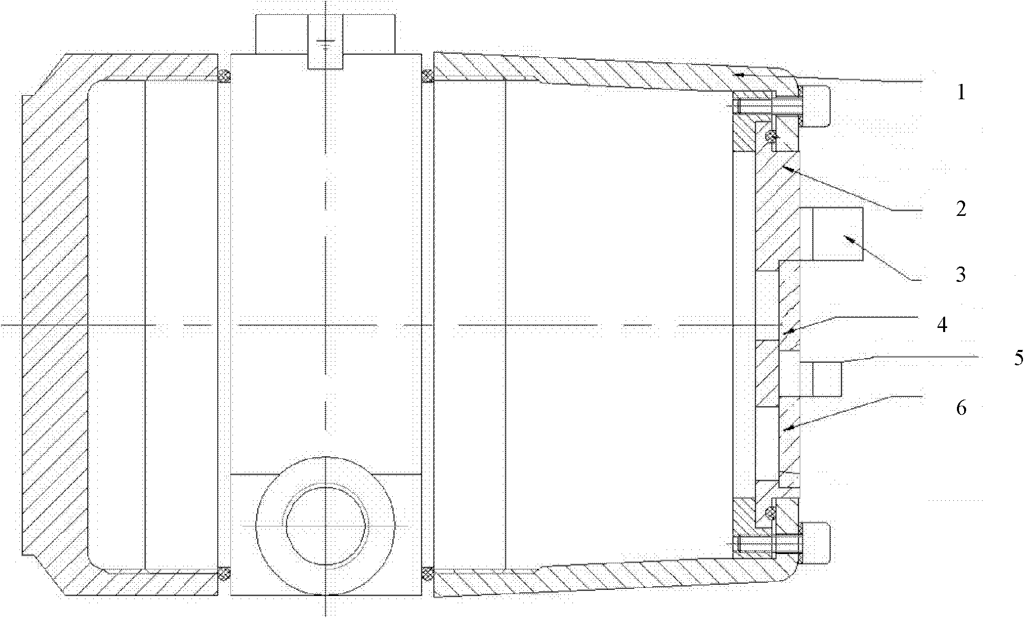
[0059] Such as figure 1 As shown, the shell of the self-inspection light source direct flame detector includes a housing 1, a panel 2, an ultraviolet self-inspection lamp holder 3, an ultraviolet window 4, an infrared self-inspection lamp holder 5 and an infrared window 6; The board is fixed on the panel, the power conversion and signal output interface board is fixed at the rear of the housing, and the ultraviolet and infrared detection boards are connected with the power conversion and signal output interface board through signal lines.

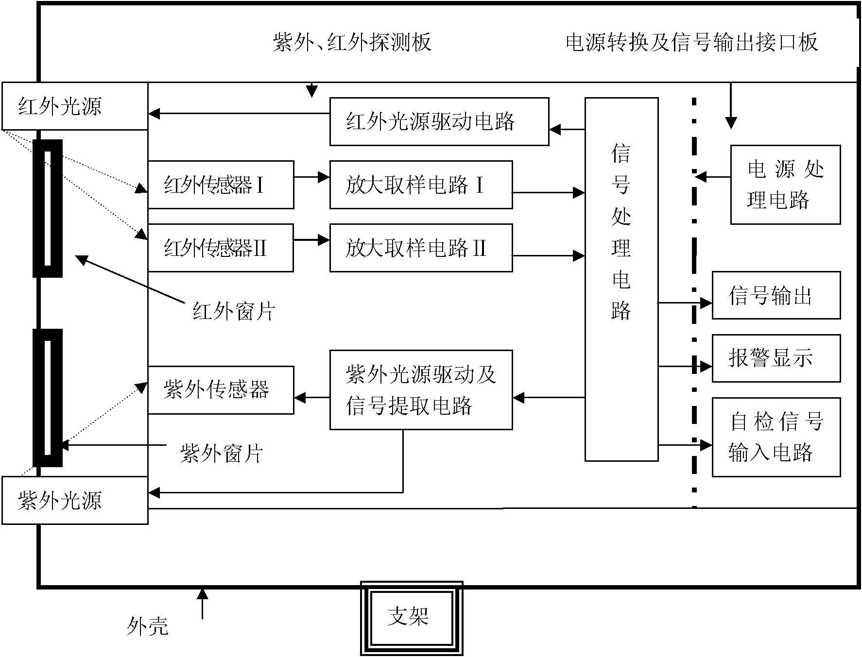
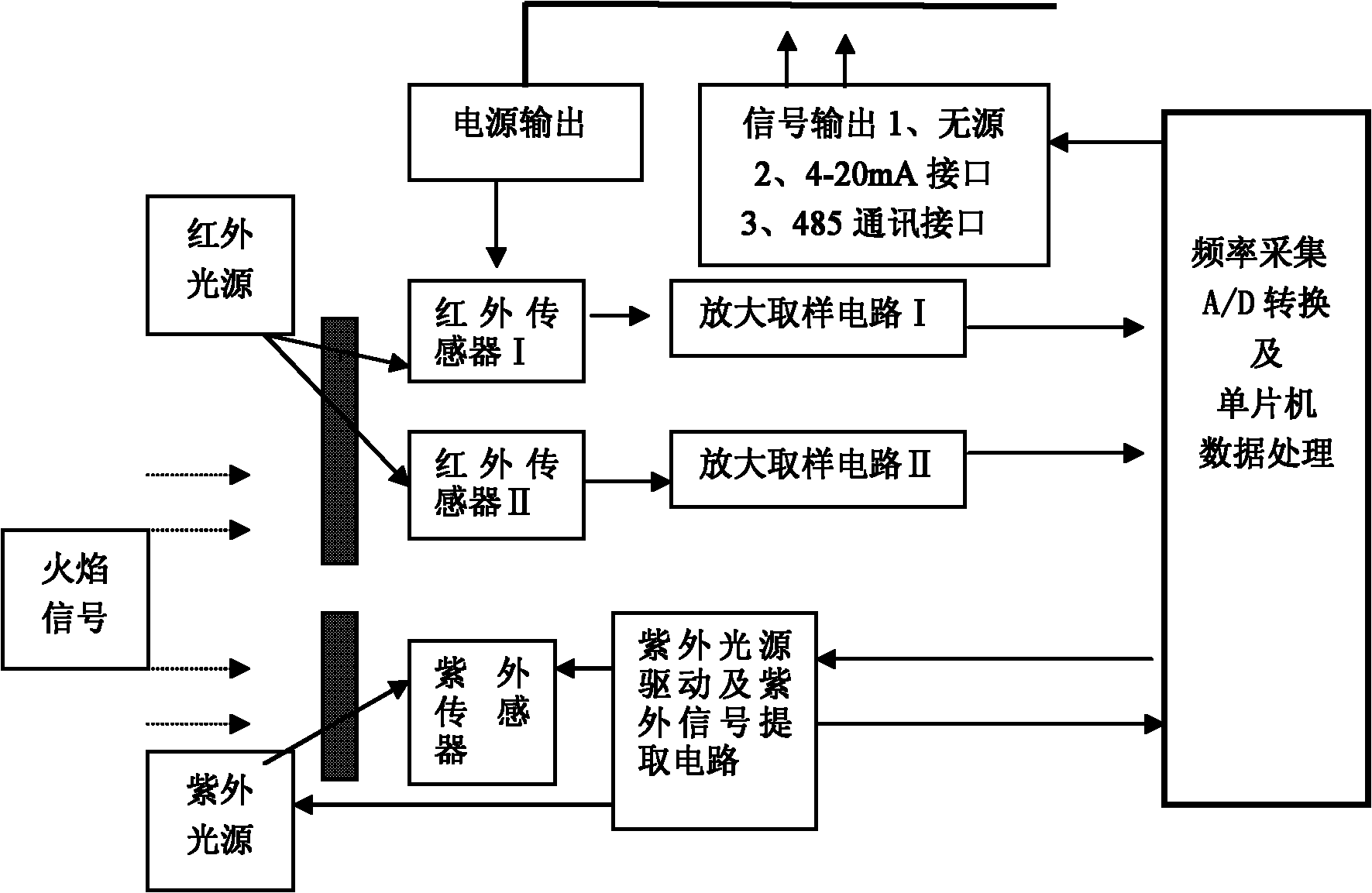
[0060] The self-inspection light source direct-ray flame detector of the present invention includes a housing, an infrared light source, an ultraviolet light source, an infrared window, an ultraviolet window, an infrared sensor I, an infrared sensor II, an ultraviolet sensor, an infrared light source driving circuit, an ultraviolet light...


PUM


Abstract

The invention discloses a direct-injection type flame detector with a self-checking light source and a flame detection method. The direct-injection type flame detector comprises a shell, an infrared light source, an ultraviolet light source, infrared windows, ultraviolet windows, an infrared sensor I, an infrared sensor II, an ultraviolet sensor, an infrared light source driving circuit, an ultraviolet light source driving and signal extraction circuit, an amplification sampling circuit I, an amplification sampling circuit II, a signal processing circuit, a power processing circuit, a signal output circuit, an alarm display module and a self-checking signal input circuit. The direct-injection type flame detector has the advantages that: a flame infrared light source is externally arrangedand self-checked; flame signal data are acquired by using the infrared sensors and the ultraviolet sensor; fire occurrence judgment which comprises infrared flame and background amplitude judgment, infrared flame and background frequency judgment, ultraviolet flame frequency signal judgment and ultraviolet and infrared composite judgment is performed; and by setting an infrared background detection wave band, when infrared interference occurs on the scene, false alarm resistance is improved, and the environmental suitability of the detector is improved.

Description

technical field [0001] The invention belongs to the field of automatic fire detection and alarm, in particular to a self-inspection light source direct-ray flame detector and a method thereof. Background technique [0002] In the early days, ordinary ultraviolet or single-band infrared flame detectors were used internationally as a means to protect the fire safety of large spaces and underground buildings. Poor, prone to false alarms. In recent years, some people have studied the use of CCD flame imaging technology to detect flames. However, the development of fire image technology has been limited to a certain extent due to the lack of basic theoretical research on early fire image detection. Therefore, in recent years, Japan, Switzerland and other countries have successively developed and successfully used dual-band infrared flame detectors for fire safety protection of large spaces and underground buildings. It can further suppress the interference of environmental inte...

Claims


Application Information

Patent Timeline
Patent Type & Authority Applications(China)
IPC IPC(8): G08B17/12
CPCG01J5/0014G01J1/0228G01J1/429G01J5/026
Inventor 王勇俞徐放梅志斌董文辉张曦
Owner SHENYANG FIRE RES INST OF MEM
Why Eureka
Try Eureka