Self-sorting type ball mill and application thereof

A ball mill and self-separation technology, applied in grain processing, etc., can solve problems such as easy full grinding and over-grinding, and achieve the effects of reducing potential energy, controlling yield, and saving production energy consumption

Active Publication Date: 2022-01-21
TIANJIN CEMENT IND DESIGN & RES INST
View PDF10 Cites 0 Cited by
  • Summary
  • Abstract
  • Description
  • Claims
  • Application Information

AI Technical Summary

Problems solved by technology

[0007] In order to solve the problem of fine powder agglomeration and easy grinding or over-grinding in the existing ball mill, the present invention provides a self-sorting ball mill, which is used to reduce the phenomenon of fine powder agglomeration or over-grinding in the ball mill, reduce the height of the workshop, and reduce the powder Reduce the investment cost of the grinding system, reduce the energy consumption of ball mill grinding, improve the grinding efficiency, increase the energy utilization rate, and promote energy saving and emission reduction

Method used


Image

  • Self-sorting type ball mill and application thereof
  • Self-sorting type ball mill and application thereof
  • Self-sorting type ball mill and application thereof

Examples


Embodiment 1

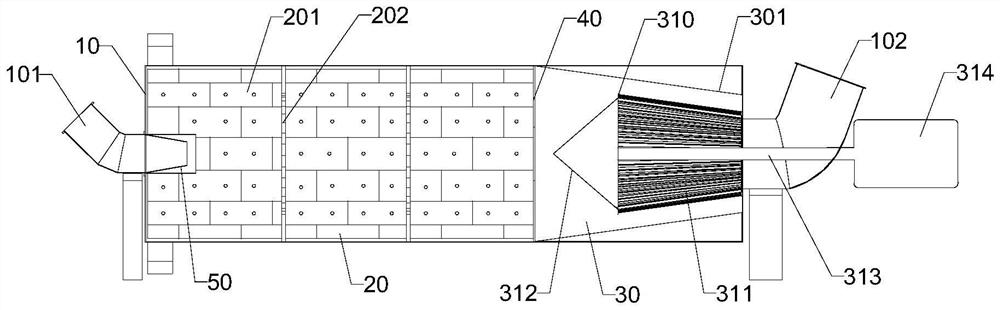
[0061] see Figure 1-5 , the present embodiment provides a self-sorting ball mill, including a cylinder body 10, a material inlet 101, and a material outlet 102. The cylinder body 10 is inclined upward from the side of the material inlet 101 to the side of the material outlet 102, and the inclination angle is 2 to 5°; the cylinder 10 is driven to rotate by the mill (not shown in the mill driving figure, specifically, the cylinder 10 can be driven to rotate by gear transmission or other means), and the cylinder 10 is driven by the feed port From 101 to the discharge port 102, a grinding bin 20 and a powder selecting bin 30 are arranged in sequence.

[0062] A grinding liner 201 is arranged on the inner wall of the cylinder 10 of the grinding chamber 20, and the grinding lining 201 is parallel to the axis of the cylinder 10; several activation rings 202 are arranged in the grinding chamber 20, which can increase the residence time of the material and prolong the time of the mate...

Embodiment 2

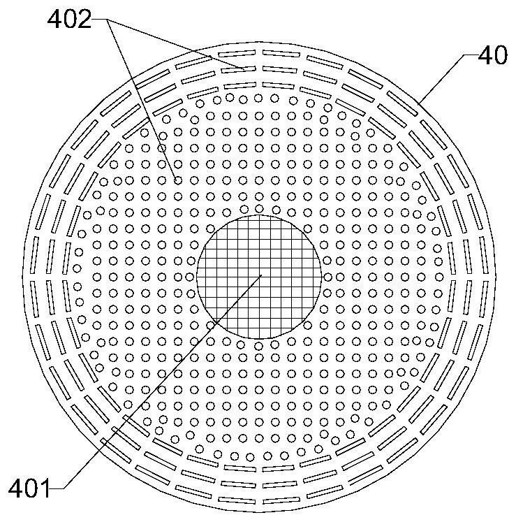
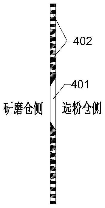
[0070] see Figure 6-8 , different from Embodiment 1, the powder selection bin 30 of this embodiment is also provided with a static powder selection machine 320, and the static powder selection machine 320 is located between the main compartment plate 40 and the dynamic powder selection machine 310 between.

[0071]The static powder separator 320 includes static blades 321, which are arranged in a conical shape. The angle between the static blades 321 and the axis of the cylinder body 10 is 45-65°. The side of the bin 30 gradually increases. One end of the static vane 321 close to the grinding bin 20 is fixed on the main compartment plate 40, and the other end is fixed on the cylinder body 10. Specifically, the other end is fixed on the inclined lining in the powder selection bin 30. On the plate 301, the joints are all connected by welding. The ratio of the length of the static vanes 321 in the axial direction to the length of the powder bin 30 is 15-25%, the width of each ...

Embodiment 3

[0076] see Figures 9 to 11 , different from Example 1, a drying bin 60 is also provided between the feed port 101 and the grinding bin 20 in this embodiment, and it is not necessary to make the feed port 101 and the grinding bin 20 as described in Embodiment 1. The included angle of the axis of the cylinder 10 is greater than 45° and an anti-scouring device 50 is set at the feed port 101. In this embodiment, a feed conveying reamer 601 is provided at the feed port 101, and the wet material passes through the feed conveying reamer 601 is conveyed into the drying bin 60 by screw.

[0077] A plurality of dispersing devices 602 are arranged in the drying bin 60 to fully disperse the materials so that the wet materials are dried in the drying bin 60; 25%, and the gap between two adjacent dispersing devices 602 is 100-400 mm.

[0078] A second main compartment plate 70 is arranged between the drying compartment 60 and the grinding compartment 20, and the thickness of the second m...


PUM


Abstract

The invention discloses a self-sorting type ball mill and application thereof. The self-sorting type ball mill comprises a barrel, a feeding port and a discharging port, and the barrel inclines upwards from the feeding port side to the discharging port side; a grinding bin and a powder selecting bin are sequentially arranged in the barrel from the feeding port to the discharging port, and a first main bin partition plate is arranged between the grinding bin and the powder selecting bin; and a static powder selecting machine and / or a dynamic powder selecting machine are / is arranged in the powder selecting bin. According to different selected materials, the dynamic powder selecting machine or the static powder selecting machine can be independently selected in the powder selecting bin, the dynamic powder selecting machine and the static powder selecting machine can be combined, and a drying bin can be arranged. Grinding and sorting of the materials can be completed in the ball mill, an external powder concentrator is not needed, the plant height and the occupied area are effectively reduced, accessory equipment is reduced, the investment cost is saved, the equipment failure rate is reduced, the production and maintenance cost is reduced, qualified fine powder generated in the grinding process can be discharged in time, excessive grinding of the materials in the ball mill is reduced, grinding power consumption is saved, and energy conservation and emission reduction of production enterprises are facilitated.

Description

technical field [0001] The invention relates to the technical field of ball mills, in particular to a self-sorting ball mill and its application. Background technique [0002] The ball mill is composed of a barrel and a grinding body. When the barrel of the ball mill rotates, the grinding body is attached to the liner of the barrel and taken away by the barrel due to inertia, centrifugal force, and friction. When it is high, it is thrown down due to its own gravity, and the thrown grinding body crushes the material under the action of gravity and impact force to realize material grinding. Due to its simple structure and good equipment reliability, the ball mill is widely used in building materials, mineral processing, metallurgy, electric power, medicine, food and chemical industries. According to different grinding environments, ball mills can be divided into dry type and wet type; according to different transmission modes, they can be divided into center drive type and ed...

Claims


Application Information

Patent Timeline
Patent Type & Authority Applications(China)
IPC IPC(8): B02C21/00B02C17/10B02C17/06B02C17/18B02C23/08B02C23/30B02C23/32
CPCB02C21/00B02C17/10B02C17/06B02C17/1835B02C17/1885B02C17/189Y02P40/10
Inventor 杜鑫聂文海刘畅豆海建秦中华
Owner TIANJIN CEMENT IND DESIGN & RES INST
Why Eureka
Try Eureka