
Intelligent micro-grid control system and intelligent power consumption management method

A management and control system and micro-grid technology, applied in transmission systems, information technology support systems, electrical components, etc., can solve the problem of inability to develop various innovative applications of networked electricity, electricity meters or power grids that do not have cloud functions and energy consumption. To solve problems such as play, to achieve the effect of efficient use of power generation facilities and electric energy, reduce electricity costs, and improve construction efficiency

Inactive Publication Date: 2012-06-13
CQI
View PDF2 Cites 13 Cited by
  • Summary
  • Abstract
  • Description
  • Claims
  • Application Information

AI Technical Summary

Problems solved by technology

Also because it is only used as a network connection for power supply, transmission and distribution, its internal structure only deals with functions related to power transmission, and cannot perform more subtle performance in terms of power consumption, nor can it improve the efficiency of other energy consumption do play
[0008] However, traditional switchboards, electricity meters or power grids hardly have cloud functions, and subsequent maintenance and upgrade costs are high and difficult, and it is also impossible to develop innovative applications for various networked electricity consumption. This is another deficiency.

Method used


Image

  • Intelligent micro-grid control system and intelligent power consumption management method
  • Intelligent micro-grid control system and intelligent power consumption management method
  • Intelligent micro-grid control system and intelligent power consumption management method

Examples


Embodiment Construction

[0028] Embodiments of the invention are described in detail below, examples of which are illustrated in the accompanying drawings. The embodiments described below by referring to the figures are exemplary only for explaining the present invention and should not be construed as limiting the present invention.

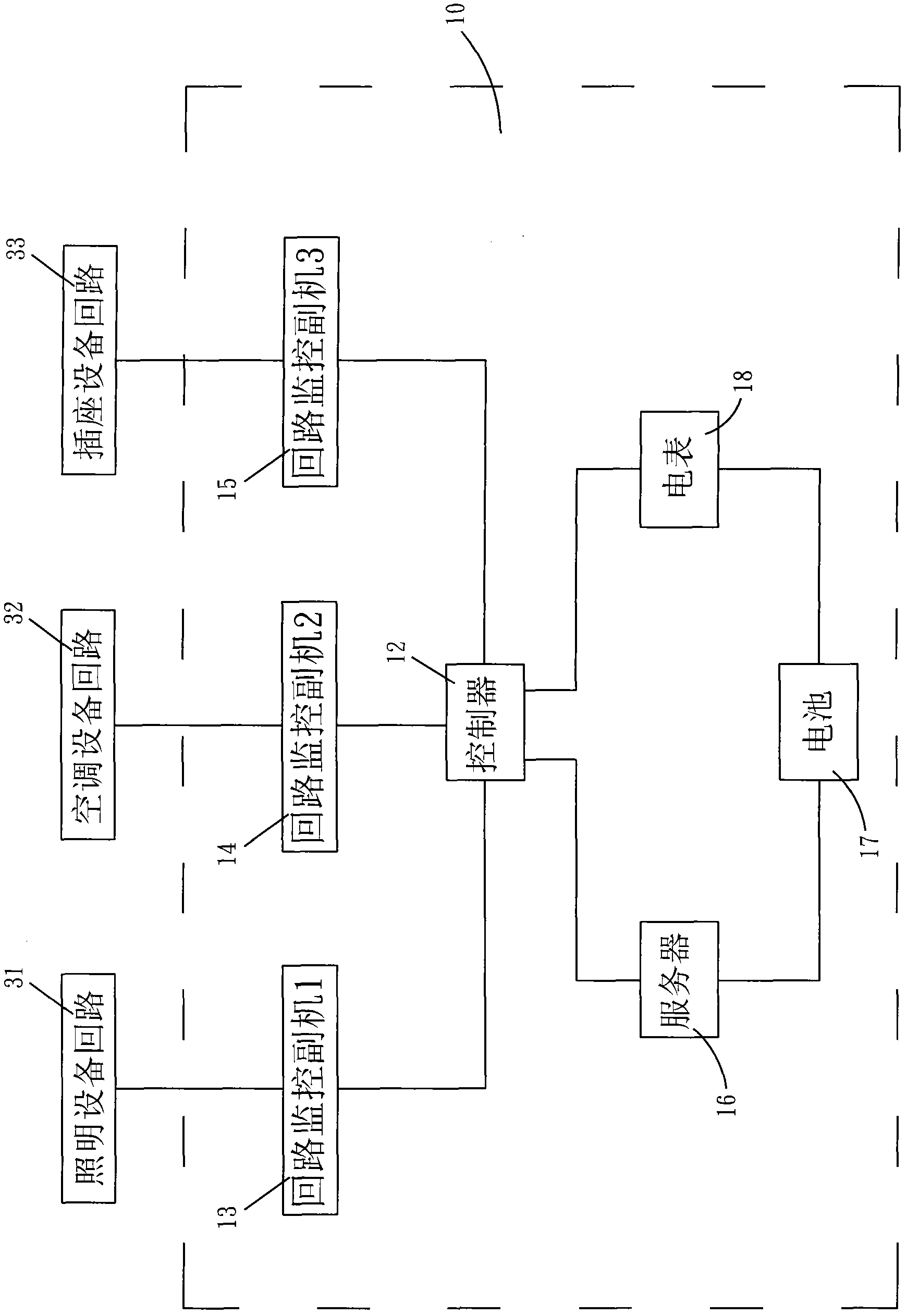
[0029] According to the smart microgrid management and control system and the smart power consumption management method according to the embodiments of the present invention, please refer to figure 1 as shown, figure 1It is a block diagram of the smart microgrid management and control system. The smart microgrid management and control system (10) includes: a controller (12), a plurality of loop monitoring auxiliary machines (13) (14) (15), a server (16), a battery (17), and an electric meter (18). One end of the first loop monitoring auxiliary machine (13) is connected to the lighting equipment circuit (31), and the other end is connected to the controller (12), which ...


PUM


Abstract

The invention discloses an intelligent micro-grid control system and an intelligent power consumption management method. The system comprises: a controller, a plurality of loop monitoring auxiliary machines, a server, an ammeter and a cell. The loop monitoring auxiliary machines respectively monitor each energy consumption equipment and read energy consumption data of the equipment loop. The controller controls a plurality of the loop monitoring auxiliary machines and transmits an energy consumption equipment running state obtained by the loop monitoring auxiliary machines and an energy consumption read value through the server. A user can read the data on a cloud platform through a computer or a mobile phone and carry out monitoring and management. When the energy consumption of the energy consumption equipment generates overload or abnormity, a warning message can be emitted so as to notify the user. Therefore, the user can grasp an abnormity state of energy consumption safety. The system possesses functions of energy consumption safety, energy consumption overload warning and energy consumption abnormity warning. Besides, a cloud service function is possessed. The running state data of each energy consumption facility can be transmitted to the cloud server. The user can remotely control the running and usage of the each energy consumption facility through an internet-connected device. The intelligent management can be realized.

Description

technical field [0001] The invention relates to a power system, in particular to an intelligent micro-grid management and control system and an intelligent power consumption management method. Background technique [0002] The traditional switchboard is usually a configuration facility that controls the circuit switches of a single type of equipment. It concentrates the switches of the power circuit in one box to make a shunt, and forms a short-circuit protection function when the power consumption is overloaded. Since most of its centralized configurations are devices with the same function, it can only control the switching lines of the same type of electrical appliances or energy-consuming facilities, without further extending other technologies and functions other than electric power. Functionally weaker. [0003] However, the non-fuse switch used in the traditional switchboard does not collect power consumption information, so it usually trips the circuit breaker in th...

Claims


Application Information

Patent Timeline
Patent Type & Authority Applications(China)
IPC IPC(8): H02J13/00H04L29/08
CPCY04S40/127Y02E60/7861Y02E60/00Y04S40/126
Inventor 吕明光
Owner CQI
Learn More