Two-stage ultrasonic vibration atomizer

A technology of ultrasonic vibration and atomizer, applied in the direction of injection device, liquid injection device, etc., can solve the problems of large diameter of atomized particles, small atomization flow rate, low atomization efficiency, etc., and achieve large power capacity and adjustable power , the effect of reducing dosage

Inactive Publication Date: 2012-06-20
SUZHOU UNIV OF SCI & TECH
View PDF4 Cites 42 Cited by
  • Summary
  • Abstract
  • Description
  • Claims
  • Application Information

AI Technical Summary

Problems solved by technology

[0007] Common mechanical atomization and ultrasonic atomization methods have problems such as complex structure, high cost, high power consumption, large atomized particle diameter, low atomization efficiency, and small atomization flow rate. In order to meet the needs of new industrial applications, the development Green and efficient atomization technology has bec

Method used


Image

  • Two-stage ultrasonic vibration atomizer
  • Two-stage ultrasonic vibration atomizer
  • Two-stage ultrasonic vibration atomizer

Examples


Embodiment 1

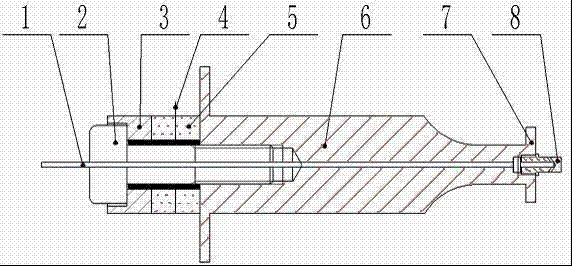
[0038] like figure 1 As shown, the two-stage ultrasonic vibration atomizer of the embodiment of the present invention adopts a piezoelectric ceramic sandwich structure, including a bolt 2 and a rear cover plate 3, a piezoelectric ceramic sheet 5, and an electrode sheet that are sequentially sleeved on the bolt. 4 and the horn 6, as well as the secondary atomizing radiation surface 7 arranged at the front end of the horn 6 and the primary atomizing nozzle 8 fixedly connected to the front end of the horn by threads. The rear cover 2, the piezoelectric ceramic sheet 3 and the electrode sheet 4 are clamped by the screw thread at the front end of the bolt 2 and the connection of the horn 6, and the rear cover 3, the piezoelectric ceramic sheet 5 and the The electrode sheet 4 is connected and compressed by the thread at the front end of the bolt 2 and the horn 6 to form a primary ultrasonic atomizing vibrator, and the secondary atomizing radiation surface 7 is located at the front ...

Embodiment 2

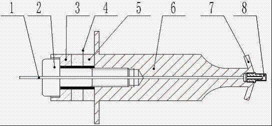
[0041] figure 2 Shown is another structural form of the two-stage ultrasonic vibrating atomizer, and figure 1 The difference is that the secondary atomization surface at the front end is a divergent radiation surface, which is suitable for occasions where the atomization area is required to be large. chemical spray nozzle 8 front ends.

Embodiment 3

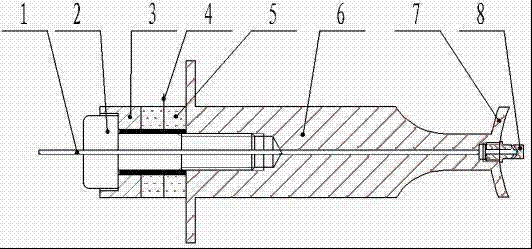
[0043] image 3 Shown is yet another structural form of the two-stage ultrasonic vibration atomizer, and figure 1 The difference is that the secondary atomization surface at the front end is a converging radiation surface, which is suitable for occasions where the atomization area is relatively concentrated. chemical spray nozzle 8 front ends.


PUM


Abstract

The invention discloses a two-stage ultrasonic vibration atomizer, which comprises a liquid conveying pipeline, a bolt, a rear cover plate, a piezoelectric ceramic plate, an electrode sheet, an amplitude transformer, a first-stage atomizing spray head and a second-stage atomizing radiation surface, wherein the rear cover plate, the piezoelectric ceramic plate and the electrode sheet are pressed by the connection between the amplitude transformer and the thread at the front end of the bolt, so as to form a second-stage ultrasonic atomizing vibrator; the first-stage atomizing spray head is connected with the front end of the amplitude transformer; and the second-stage atomizing radiation surface is clamped between the front end of the amplitude transformer and the rear end of the first-stage atomizing spray head. According to the invention, the vibrator part adopts a sandwich transducer structure, and has high power capability; the first-stage atomizing is realized by the micro-spraying holes on the first-stage atomizing spray head; the second-stage atomizing is realized by ultrasonic vibration; and through two-stage atomizing, the two-stage ultrasonic vibration atomizer has the advantages of small gas atomizing grains and the like, and can be applied to the fields of cooling of mechanical processing and cutting heat, air moistening, medical treatment, dedusting, deodorizing, weaving, printing and dyeing, tobacco, flowers, papermaking, electronics, spray-coating, chemical industry, granulating, fungus culturing, fruit storage and the like.

Description

technical field [0001] The invention relates to the field of ultrasonic vibration atomization utilizing the piezoelectric effect, in particular to a two-stage ultrasonic vibration atomizer. Background technique [0002] In many fields such as cooling, air humidification, medical treatment, dust removal, deodorization, textile, printing and dyeing, tobacco, flowers, telecommunications, papermaking, electronics, landscape, spraying, steel, chemical industry, cleaning, granulation, fungus cultivation, fruit storage, etc. Both need to atomize the liquid medium. The commonly used atomization methods are: [0003] (1) Mechanical atomization [0004] Pressurize the liquid, and inject it into the static or low-speed airflow from the nozzle at high speed and high pressure, and the injection speed increases; when the liquid is ejected, due to the sudden decrease in pressure, the liquid will drop by the joint action of surface tension, viscosity and air resistance. , smooth flow,...

Claims


Application Information

Patent Timeline
IPC IPC(8): B05B17/06
CPCB05B17/063
Inventor 李华殷振曹自洋宋克峰赵江江谢鸥王广勋陈玉荣汪帮富齐文春
Owner SUZHOU UNIV OF SCI & TECH
Why Eureka
Try Eureka