
Encapsulation base plate surface electroplating method

A technology for packaging substrates and electroplating materials, which is applied to circuits, electrical components, semiconductor devices, etc. It can solve the problems of poor appearance of gold surface color difference, poor wire bonding, thin point-shaped bubble interface, etc., and improve the plating quality rate. And the color difference of the plating surface, improve the excellent rate of wire bonding, strong fluidity and the effect of

Active Publication Date: 2012-06-20
SHENNAN CIRCUITS
View PDF7 Cites 9 Cited by
  • Summary
  • Abstract
  • Description
  • Claims
  • Application Information

AI Technical Summary

Problems solved by technology

[0004] Taking gold plating as an example, the current gold-plating dry film process in the industry is generally carried out at a high temperature of more than 110°C. The anti-plating dry film has better fluidity and filling properties at high temperatures, because the copper surface and the ink surface of the package substrate There is a height difference, and the high-temperature film is very easy to produce point-like bubbles on the copper surface. The interface of the point-like bubbles is very thin, and may break during the electroplating process, resulting in poor gold plating, which eventually leads to poor wiring on the client side and color difference in the appearance of the gold surface. Bad and other issues

Method used


Image

  • Encapsulation base plate surface electroplating method
  • Encapsulation base plate surface electroplating method
  • Encapsulation base plate surface electroplating method

Examples


Embodiment Construction

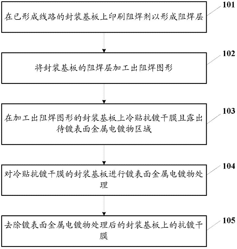
[0022] The embodiment of the present invention provides a surface electroplating method of a package substrate, in order to improve the plating yield and the color difference of the plated surface of the metal plated surface of the package substrate.

[0023] The following will clearly and completely describe the technical solutions in the embodiments of the present invention with reference to the accompanying drawings in the embodiments of the present invention. Obviously, the described embodiments are only some, not all, embodiments of the present invention. Based on the embodiments of the present invention, all other embodiments obtained by persons of ordinary skill in the art without creative efforts fall within the protection scope of the present invention.

[0024] The following describes in detail respectively through the examples.

[0025] An embodiment of the method for electroplating the surface of the packaging substrate of the present invention includes: printing a...


PUM


Abstract

The embodiment of the invention discloses an encapsulation base plate surface electroplating method, which comprises the steps that: soldering resistance agents are printed on an encapsulation base plate with formed circuits for forming a soldering resistance layer; soldering resistance patterns are processed on the soldering resistance layer of the encapsulation base plate; a plating resistance dry film is pasted on the encapsulation base plate with the processed soldering resistance patterns in a cold way, and in addition, a surface metal electroplate object region to be plated is exposed, wherein the film pasting temperature of the plating resistance dry film cold pasting is lower than the melting point temperature of the plating resistance dry film; the surface metal electroplate plating treatment is carried out on the encapsulation base plate pasted with the plating resistance dry film in the cold way; and the plating resistance dry film on the encapsulation base plate after the surface metal electroplate plating treatment is removed. The technical scheme of the embodiment of the invention is favorable for reducing the plating surface color difference and improving the plating acceptance rate of the encapsulation base plate plated with surface metal electroplates.

Description

technical field [0001] The invention relates to the field of circuit board manufacturing, in particular to a surface electroplating method of a packaging substrate. Background technique [0002] Packaging substrates (also called carrier boards) are printed circuit boards used to carry electronic components (such as chips). [0003] In the process of plating the surface metal plating (such as gold) on the packaging substrate, it is necessary to paste the anti-plating dry film on the area that does not need to be plated with the surface metal plating. [0004] Taking gold plating as an example, the current gold-plating dry film process in the industry is generally carried out at a high temperature of more than 110°C. The anti-plating dry film has better fluidity and filling properties at high temperatures, because the copper surface and the ink surface of the package substrate There is a height difference, and the high-temperature film is very easy to produce point-like bubbl...

Claims


Application Information

Patent Timeline
IPC IPC(8): C25D5/02C25D7/12H01L21/48
Inventor 黄永民刘良军杨海龙杨智勤
Owner SHENNAN CIRCUITS
Learn More