Vacuum impregnation device and method of fiber composite material

A fiber composite material, vacuum impregnation technology, applied in the processing of textile materials, liquid/gas/vapor textile processing, textiles and papermaking, etc. Guaranteed uniformity, simple operation and improved impregnation effect

Inactive Publication Date: 2012-06-20
YANSHAN UNIV
View PDF7 Cites 11 Cited by
  • Summary
  • Abstract
  • Description
  • Claims
  • Application Information

AI Technical Summary

Problems solved by technology

For example, after the impregnation of the fabric and the subsequent drying process, the internal stress caused by the uneven distribution of the resin will cause pits or wrinkles on the surface of the fabric, which will affect the flatness; the content...

Method used


Image

  • Vacuum impregnation device and method of fiber composite material
  • Vacuum impregnation device and method of fiber composite material

Examples


Embodiment 1

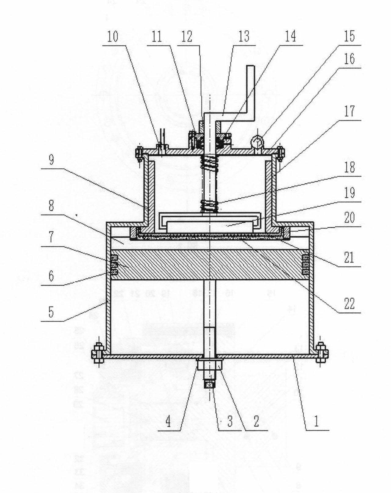
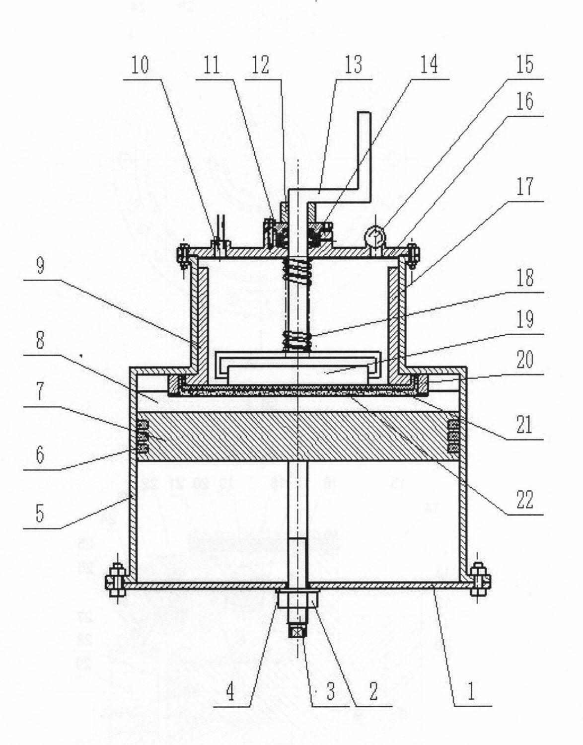
[0015] exist figure 1 In the schematic diagram of the mechanism of a vacuum impregnation device for fiber composite materials shown, the cylinder body 5 is convex, and its bottom is fixed on the frame 1 with bolts. Pass through the through hole, and fix it on the frame with the feed screw nut 2, a sealing gasket 4 is provided between the nut and the frame, and the lower end surface of the piston 7 equipped with the sealing ring 6 is connected with the end surface of the feed screw column, The upper end face of the piston is fixed to the PTFE plate 8 with grooves. Liners 9 are arranged on both inner sides of the raised part of the cylinder body, a support net 21 is fixed on the lower end face of the bush, and squeeze sleeves 20 are provided at both ends of the support net. Both ends of the upper cover of the sealing chamber 16 are fixed on the top of the cylinder body with bolts. The rotating shaft 13 passes through the through hole of the upper cover of the sealing chamber, a...

Embodiment 2

[0019] The method of vacuum impregnating the fabric using the equipment of Example 1: first, the glass fiber / PTFE fabric is laid flat on the support net, the support net is placed on the lower end surface of the bushing, and the support net and the fabric are fixed by a squeeze sleeve on the bushing; fix the grooved PTFE plate on the upper face of the piston. Spray a layer of resin evenly into the groove of the PTFE board through the paint spray gun, and the amount of resin sprayed is determined by the mass difference between the front and back of the paint spray gun measured by the electronic balance.

[0020] Then, after vacuuming the vacuum impregnation device to 50kpa, close the filling / deflation port. Relying on the spiral motion to push the piston displacement, so that the fiber fabric is in contact with the resin for impregnation; adjust the spring compression between the rotating shaft and the cylinder to maintain a certain pressure between the PTFE roller and the supp...


PUM


Abstract

The invention provides a vacuum impregnation device of a fiber composite material. A cylinder of the vacuum impregnation device is convex, the bottom of the vacuum impregnation device is fixed on a rack; a feeding screw nut for a feeding screw post is fixed on the rack; the lower end surface of a piston provided with a sealing ring is connected with the end surface of the feeding screw post, and the upper end surface of the piston is fixed together with a PTFE (Polytetrafluoroethylene) plate; supporting nets are fixed on the lower end surfaces of bushes at two inner sides of the cylinder; thetop of the cylinder is provided with an upper cover of a sealing cavity; a rotating shaft passes through a through hole in the upper cover of the sealing cavity, and the lower end surface of the rotating shaft is connected with a PTFE roller; and the upper cover of the sealing cavity is also provided with a gas charging/discharging hole and a pressure gauge. When the vacuum impregnation device isused, an appointed amount of resin is sprayed uniformly in a groove of the PTFE plate through a paint spray gun, evacuation is carried out, the rotating shaft is rotated to drive the PTFE roller to rotate on the supporting nets to evict remained air bubbles in a fabric and the resin, then the pressure in the device is released, the piston is withdrawn by using the feeding screw post, and the fabric is taken down to continuously dry. The vacuum impregnation device is simple in operation and capable of controlling the content of impregnation resin, ensuring the uniformity of the impregnation resin and effectively improving the impregnation effect of the fabric.

Description

technical field [0001] The invention relates to the technical field of impregnation equipment, in particular to an impregnation device for fiber braided materials. Background technique [0002] Fiber braided composite self-lubricating materials are woven from PTFE (polytetrafluoroethylene) fibers with low friction coefficient and reinforcing fibers, such as aramid, carbon fiber, glass fiber and other high-performance fibers. When working, the PTFE fiber acts as a lubricant, while the reinforcing fiber plays the role of bearing load and improving bonding performance. [0003] At present, for the impregnation device of fiber-woven composite materials, such as "Impregnation Equipment for Warp and Weft Overlapping Non-woven Composite Materials" (Chinese Patent 201645834 U), a kind of impregnation device for warp and weft overlapping non-woven composite materials is disclosed; "Adjusting Fabric Warp and Weft "Method and device for impregnating effect" (Chinese Patent No. CN 1019...

Claims


Application Information

Patent Timeline
IPC IPC(8): D06B3/18D06B23/00
Inventor 杨庆祥杨育林齐效文范兵利张青梅
Owner YANSHAN UNIV
Why Eureka
Try Eureka