
Efficient and energy-saving electric heating warmer

A high-efficiency, energy-saving, heater technology, applied in heating methods, electric heating systems, lighting and heating equipment, etc., can solve the problems of high operating costs, short service life of radiators, high energy and water consumption rates, and achieve low operating costs. , Solve the effect of slow heating and simple structure

Inactive Publication Date: 2012-06-20
中山市东凤镇科盛五金电器配件厂(普通合伙)
View PDF5 Cites 2 Cited by
  • Summary
  • Abstract
  • Description
  • Claims
  • Application Information

AI Technical Summary

Problems solved by technology

But for many years, urban central heating or rural individual heating have always used ordinary radiators as heat dissipation components. Hot water or steam flows directly through the radiators, and then dissipates heat into the air through the radiators to achieve indoor heating; its disadvantages The disadvantages are its low heat transfer efficiency, high energy and water resource loss rate, loud steam pipe noise, rapid corrosion of heating pipe network and equipment, short service life of radiators, high pressure in pipes, and certain potential safety hazards.
In view of the above problems, the existing technology can adopt the electric heating method, but there are also certain defects to a certain extent, such as when the indoor temperature rise rate is slow, in order to meet the heating and heat preservation needs, the electric heater must be operated for a long time to be able to Guaranteed; the effective heating area is small, which can only meet the heating needs of small rooms; the operating cost is high and the energy consumption is high

Method used


Image

  • Efficient and energy-saving electric heating warmer
  • Efficient and energy-saving electric heating warmer
  • Efficient and energy-saving electric heating warmer

Examples


Embodiment Construction

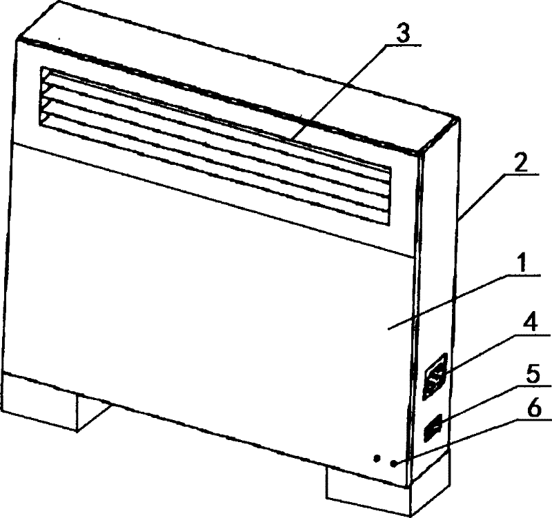
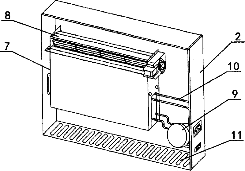
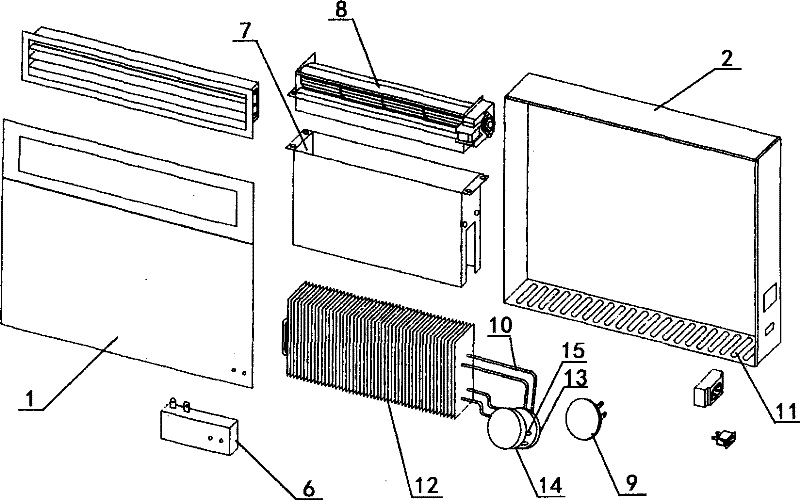
[0019] Such as Figure 1-3 As shown, the high-efficiency energy-saving electric heating heater according to the embodiment of the present invention includes a casing 2, a loop heating unit 7, and a heating plate 9. A front panel with a decorative layer is installed on the casing 2 and the outer surface. The cover plate 1 is also provided with an air outlet 3 at the upper or lower position of the front cover plate 1. At the same time, a loop control unit 7 with an outer layer of the windshield is installed in the inner cavity of the casing 2 and is located in the loop control unit. Several rows of condensers 12 are arranged inside 7; the top of the loop control unit 7 is connected to the induced draft fan 8 and the position of the air grille of the induced draft fan 8 is at the air outlet 3. Disk 9, a liquid storage chamber 14 and an evaporator 13 are respectively arranged on both sides of the heating disk 9, and the liquid storage chamber 14 and the evaporator 13 are connected...


PUM


Abstract

The invention relates to an efficient and energy-saving electric heating warmer, which comprises a shell, a loop heating unit and a heating plate. A front cover plate with a decorative layer is mounted on the outer surface of the shell, a loop control unit with a fan cover outer layer is mounted in an inner cavity of the shell, a plurality of rows of condensers are arranged inside the loop control unit, the outside of the loop control unit is connected with the heating plate through an air duct, a liquid storage chamber and an evaporator are arranged on two sides of the heating plate respectively, and the liquid storage chamber and the evaporator are connected with each other through a liquid guide pipe to form a circulating pipeline. The efficient and energy-saving electric heating warmer has the advantages that a loop heat pipe is used as a conductor, heat is transferred by means of evaporation and condensation of media, a large amount of heat can be transferred under the conditions of small temperature difference and long distance, the heating area of the heating plate is enlarged, hot air among radiating fins is continuously delivered into air through an induced draft fan, heat energy is sufficiently used, and the problems of slow temperature rise, small heating area, high energy consumption and the like of most existing products are fundamentally solved.

Description

technical field [0001] The invention relates to a heating device, in particular to a high-efficiency and energy-saving electric heating heater. Background technique [0002] Current heating methods, especially in cold regions, all use central heating methods widely. But for many years, urban central heating or rural individual heating have always used ordinary radiators as heat dissipation components. Hot water or steam flows directly through the radiators, and then dissipates heat into the air through the radiators to achieve indoor heating; its disadvantages The disadvantages are its low heat transfer efficiency, high loss rate of energy and water resources, high noise of steam pipes, rapid corrosion of heating pipe network and equipment, short service life of radiators, high pressure inside pipes, and certain potential safety hazards. In view of the above problems, the existing technology can adopt the electric heating method, but there are also certain defects to a cert...

Claims


Application Information

Patent Timeline
IPC IPC(8): F24D13/02F24D19/00F24D19/10
CPCY02B10/70
Inventor 邹照添
Owner 中山市东凤镇科盛五金电器配件厂(普通合伙)
Features
  • Generate Ideas
  • Intellectual Property
  • Life Sciences
  • Materials
  • Tech Scout
  • Unparalleled Data Quality
  • Higher Quality Content
  • 60% Fewer Hallucinations
Learn More