Method for accurately measuring narrow pulse modulation parameter

A technology of modulation parameters and narrow pulses, which is applied in pulse characteristic measurement, modulation depth measurement, transmission monitoring, etc. It can solve problems such as poor sensitivity, inability to linearize the detector, compensation of frequency response and temperature response, and small dynamic range of measurement.

Inactive Publication Date: 2012-06-20
CHINA ELECTRONIS TECH INSTR CO LTD
View PDF5 Cites 23 Cited by
  • Summary
  • Abstract
  • Description
  • Claims
  • Application Information

AI Technical Summary

Problems solved by technology

However, due to the limitation of the sensitivity of the oscilloscope, the measurement dynamic range is small and the sensitivity is poor; and because the pulse signal is measured by the oscilloscope after passing through the dete

Method used


Image

  • Method for accurately measuring narrow pulse modulation parameter
  • Method for accurately measuring narrow pulse modulation parameter
  • Method for accurately measuring narrow pulse modulation parameter

Examples


Embodiment Construction

[0041] The present invention will be described in further detail below in conjunction with the accompanying drawings.

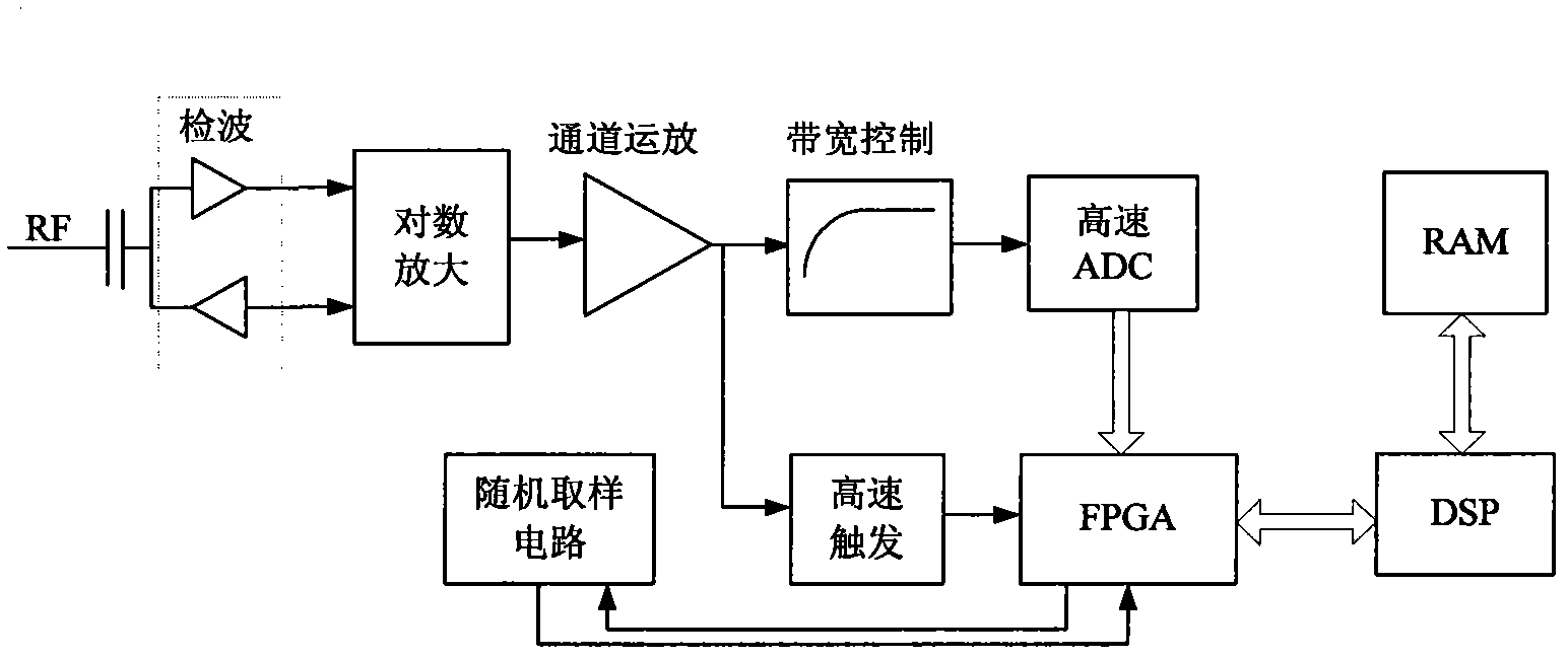
[0042] The method for accurately measuring narrow pulse modulation parameters described in the present invention is to figure 1 Based on the narrow pulse measurement circuit diagram shown, the specific steps are:

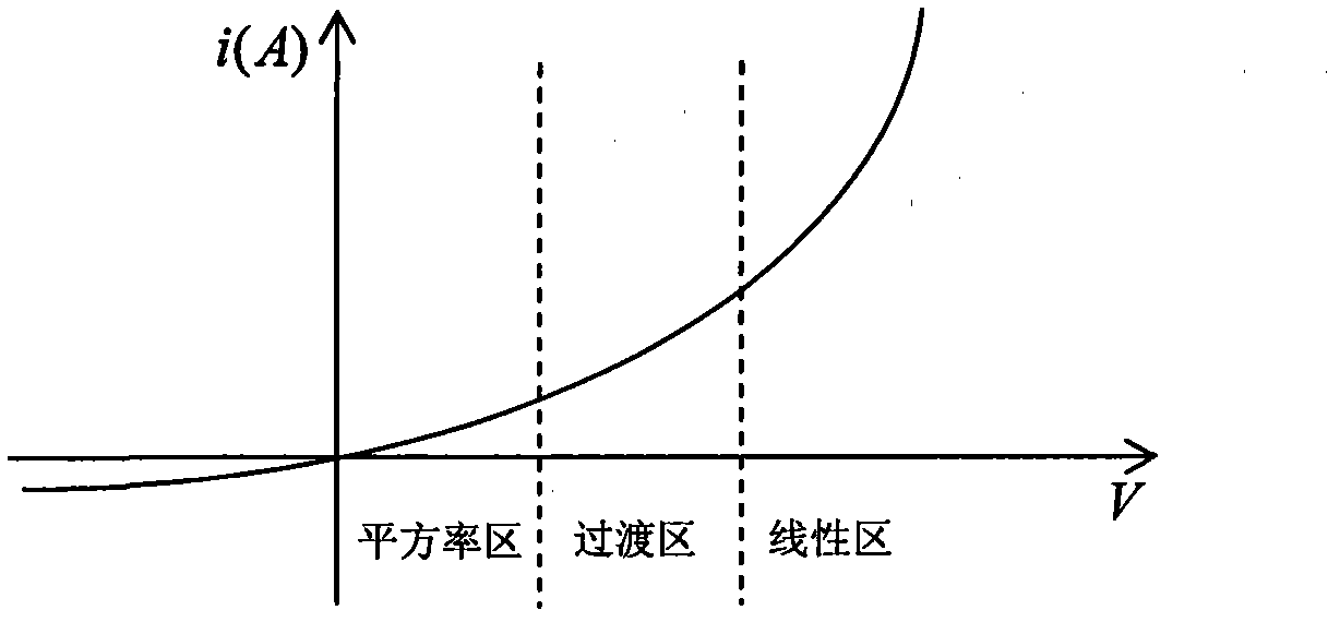
[0043] The narrow pulse modulation signal RF is firstly detected by a double diode detector, and the positive and negative pulse envelope signals are output.

[0044] The two-way pulse envelope signal output by the detector is sent to the broadband logarithmic amplifier for logarithmic amplification; the purpose of sending it to the broadband logarithmic amplifier for logarithmic amplification is to adjust the dynamic range of the detection output, which is convenient for back-end channel processing and high-speed ADC module. A / D conversion (sampling);

[0045] After the signal output by the logarithmic amplifier is linearly adjusted by the chann...


PUM


Abstract

The invention relates to a method for accurately measuring a narrow pulse modulation parameter. According to the method, a narrow pulse modulation signal RF passes through a double-diode detector, a logarithmic amplifier and a channel operational amplifier unit in sequence and is divided into two paths of signals, one path of signal is fed into a high-speed analog-to-digital converter (ADC) module for analog-to-digital (A/D) conversion by a bandwidth control unit, the other path of signal is fed into a high-speed trigger circuit, the high-speed ADC module triggers A/D conversion according to a pulse signal generated by the high-speed trigger circuit, and effective ADC data is acquired, fed into a field programmable gate array (FPGA) and stored in the FPGA according to a trigger signal generated by the high-speed trigger circuit; and a digital signal processor (DSP) unit reads the effective ADC data from the FPGA, processes the data and stores an operation result in a high capacity random access memory (RAM). By the method for accurately measuring the narrow pulse modulation parameter, the narrow pulse modulation parameter with the minimal pulse width of 30ns and the dynamic range of -27 to +20dBm can be measured, and both the time parameter and the amplitude parameter of the narrow pulse modulation signal can be measured.

Description

technical field [0001] The invention relates to the measurement of narrow pulse modulation signals, in particular to a method for accurately measuring narrow pulse modulation parameters. Background technique [0002] Pulse modulation can be widely used in radar and communication fields. For the measurement of narrow pulse modulation signals, there are mainly the following two methods: [0003] 1. Spectrum analysis and measurement method: a broadband spectrum analyzer can be used to measure narrow pulse modulation signals. Through the frequency spectrum analysis of the pulse modulation signal, information such as the pulse width, pulse period and pulse amplitude of the pulse modulation signal can be obtained. [0004] Using the spectrum analysis measurement method has the advantage of a wide dynamic range, but the disadvantage is that it can only measure the pulse width, pulse period and pulse amplitude information of the narrow pulse modulation signal, but cannot measure th...

Claims


Application Information

Patent Timeline
IPC IPC(8): G01R29/06G01R29/02H04B17/00
Inventor 李金山徐达旺宁泽洪董占勇
Owner CHINA ELECTRONIS TECH INSTR CO LTD
Why Eureka
Try Eureka