
Microwave beam focusing rotary scanning device

A technology of rotating scanning and microwave beams, which is applied in the direction of measuring devices, waveguide horns, radio wave measuring systems, etc., can solve the problems of difficult control of focus movement, relatively high processing accuracy requirements, and increased system complexity, etc., to achieve defocused focusing Convenience, easy focus movement, and easy-to-achieve effects

Inactive Publication Date: 2012-06-20
UNIV OF ELECTRONICS SCI & TECH OF CHINA
View PDF3 Cites 17 Cited by
  • Summary
  • Abstract
  • Description
  • Claims
  • Application Information

AI Technical Summary

Problems solved by technology

The focusing lens is realized by a periodic structure composed of metal grids or metal sheets. This structure is more complicated to realize and requires higher processing accuracy.
Although the lens of the homogeneous medium can achieve focusing, the volume structure is relatively large, which is not conducive to the miniaturization of the system
At the same time, adopting the method of moving the feed source to achieve defocused movement of the focal point of the dielectric lens not only increases the complexity of the system, but also the movement of the feed source will affect the focusing effect, and the movement of the focus point is also difficult to control

Method used


Image

  • Microwave beam focusing rotary scanning device
  • Microwave beam focusing rotary scanning device
  • Microwave beam focusing rotary scanning device

Examples


Embodiment

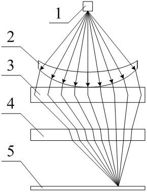
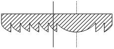
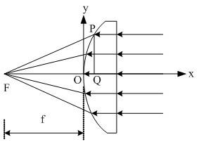
[0024] Such as figure 1 , figure 2 and image 3 As shown, the microwave beam focusing and rotating scanning device includes a horn antenna 1, a meniscus lens 2, a defocusing focusing antenna 3, a focusing plate 4 and a focusing plate 5, wherein the horn antenna 1, the meniscus lens 2, the defocusing The focusing antenna 3, the focusing plate 4 and the focusing plate 5 are arranged coaxially. Horn antenna 1 is arranged on the top of meniscus lens 2, and it is used for emitting the linearly polarized spherical electromagnetic wave, and horn antenna 1 is the microwave source of whole scanning device, provides microwave energy for whole device, when horn antenna 1 is positioned at focal length and changes When in position, it can adjust the direction of the beam. The upper end surface of the meniscus lens 2 is indented to form a spherical surface, and its lower end surface forms an ellipsoid, and the bottom of the meniscus lens 2 is in contact with the upper end surface of the...


PUM


Abstract

The invention discloses a microwave beam focusing rotary scanning device, which comprises a horn antenna (1), a crescent lens (2), an offset focusing antenna (3) and a focus adjustment board (4) which are arranged coaxially, wherein the horn antenna (1) is arranged above the crescent lens (2); the bottom of the crescent lens (2) is contacted with the upper end face of the offset focusing antenna (3); and the focus adjustment board (4) is arranged below the offset focusing antenna (3). By adoption the structure, the whole microwave beam focusing rotary scanning device has a simple structure and a small volume, and is easy to implement; and according to the microwave beam focusing rotary scanning device, electromagnetic waves can be moved conveniently in a focus offsetting manner, a focusing manner and a focal point manner.

Description

technical field [0001] The invention relates to microwave imaging detection, in particular to a microwave beam focusing rotary scanning device. Background technique [0002] In microwave imaging detection, the system usually has high requirements for antenna gain, but a single antenna is usually difficult to meet the requirements. In order to increase the gain of the antenna, a phased array antenna is usually used to achieve high gain. The phased array antenna achieves high gain and focusing by controlling the feeding phase and amplitude of the antenna array unit, and gathers more energy to the target to be detected. However, the structure of realizing the phased array antenna is relatively complicated, and the phased array antenna needs a complicated feeding network, which increases the complexity of the structure. At the same time, the focal point of the phased array antenna is relatively fixed, and complex phase control is required to realize the movement of the focal po...

Claims


Application Information

Patent Timeline
Patent Type & Authority Applications(China)
IPC IPC(8): G01S13/89H01Q19/06H01Q13/02
Inventor 赵志钦吴江牛杨德强聂在平
Owner UNIV OF ELECTRONICS SCI & TECH OF CHINA
Learn More