
Single-direction inclined-shaft profiling precision grinding method of array optical elements of micro circular troughs

A technology for optical components and precision grinding, which is applied in the direction of optical surface grinders, grinding/polishing equipment, grinding machines, etc. It can solve the problems of low grinding efficiency, easy wear of grinding wheels, and large difference in surface roughness, etc., to achieve grinding The effect of improving machining efficiency, improving machining accuracy, and reducing surface roughness

Inactive Publication Date: 2013-09-18
HARBIN INST OF TECH
View PDF9 Cites 0 Cited by
  • Summary
  • Abstract
  • Description
  • Claims
  • Application Information

AI Technical Summary

Problems solved by technology

[0005] The present invention aims to solve the problems that the surface roughness of the micro-arc grooves ground in different feeding directions by the existing micro-arc groove array optical element grinding method is relatively different, the grinding wheel is easy to wear during processing, and the grinding processing efficiency is low, and further Provided is a single-direction oblique-axis profiling precision grinding method for micro-arc groove array optical elements

Method used


Image

  • Single-direction inclined-shaft profiling precision grinding method of array optical elements of micro circular troughs
  • Single-direction inclined-shaft profiling precision grinding method of array optical elements of micro circular troughs

Examples


specific Embodiment approach 1

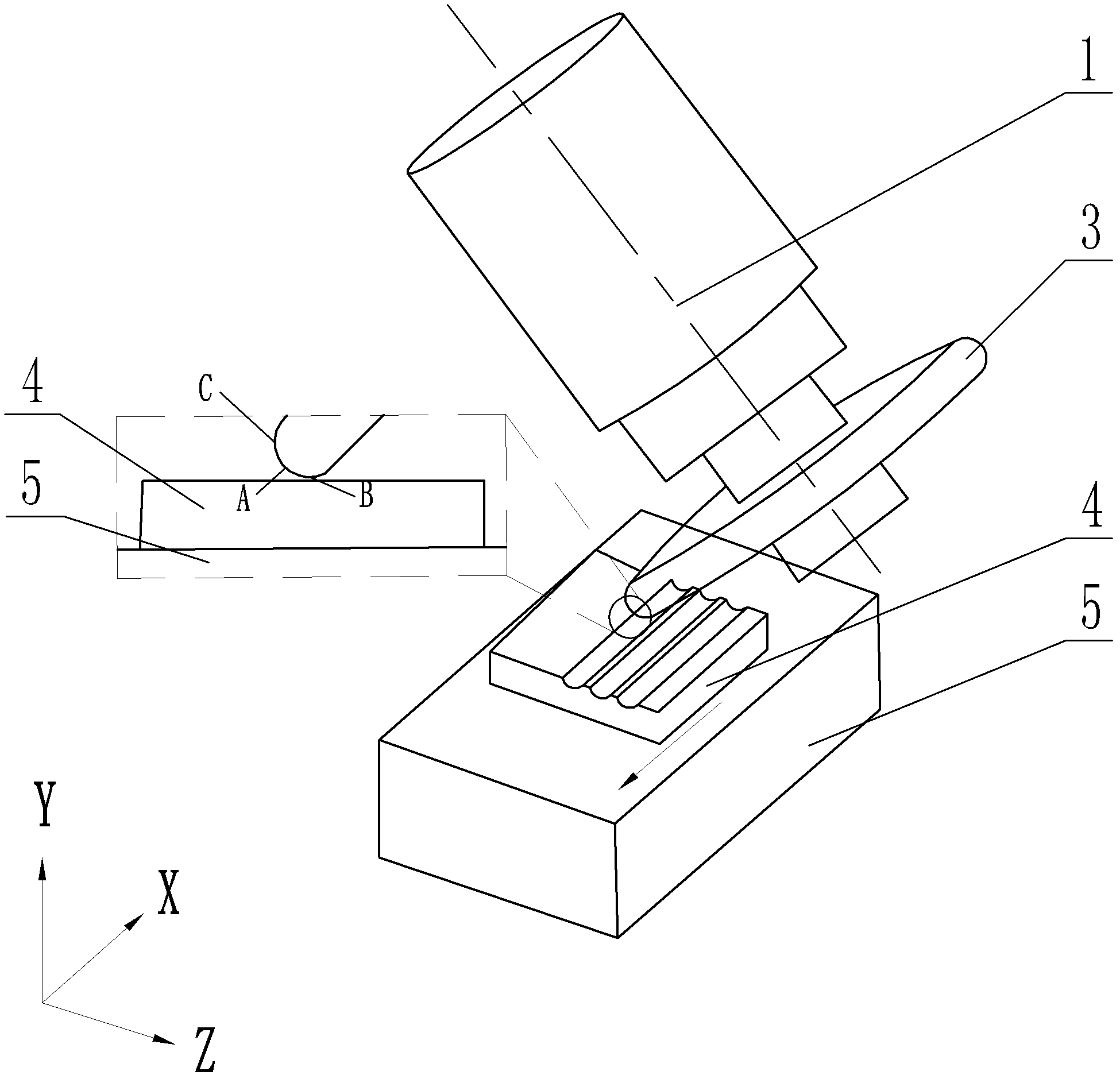
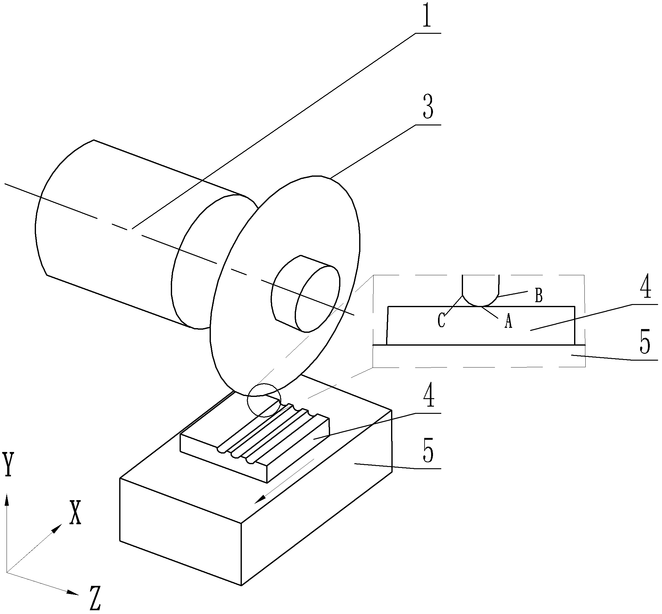
[0014] Specific implementation mode one: combine figure 1 Explain that the single-direction oblique-axis profiling precision grinding method of the micro-arc groove array optical element described in this embodiment is realized according to the following steps:

[0015] Step 1. Fix the workpiece 4 to be ground on the upper surface of the workbench 5 of the precision grinding machine, and rotate the profiling grinding wheel 3 so that the rotation axis 1 of the profiling grinding wheel 3 forms an angle of 45 degrees with the plane where the surface of the workpiece 4 to be ground is located, so that The first lowest point B of the profiling grinding wheel 3 becomes the grinding center point;

[0016] Step 2. Adjust the profiling grinding wheel 3 to the initial point of the first arc groove to be processed, so that the workpiece 4 to be ground is fed in the opposite direction of the X axis along with the precision grinding machine table 5, and the rotation direction of the profi...


PUM


Abstract

The invention discloses a single-direction inclined-shaft profiling precision grinding method of array optical elements of micro circular troughs, and relates to a precision grinding method of array optical elements of micro circular troughs. The invention aims at solving the problems that the surface roughness of micro circular troughs ground by the current grinding method of the array optical elements of the micro circular troughs in different feeding directions has large difference, a grinding wheel is easily abraded in processing, and the grinding processing efficiency is low. The single-direction inclined-shaft profiling precision grinding method comprises the following steps of: 1, causing the axis of rotation of a profiling grinding wheel and the upper surface of a workpiece to be ground to form an included angle of 45 degrees, and causing the first lowest point of the profiling grinding wheel to become a grinding center point; 2, causing the workpiece to be ground to feed along the reverse direction of an X axis and to process micro circular troughs of all arrays in a single direction along with a workbench of a precision grinder; 3, and causing the axis of rotation of the grinding wheel and a plane with the surface of the workpiece to form an included angle of 135 degrees, causing the second lowest point of the grinding wheel to become the grinding center point, and then processing the circular troughs according to the step 2. The precision grinding method disclosed by the invention is used for processing array optical elements of the micro circular troughs.

Description

technical field [0001] The invention relates to a precision grinding method for micro-arc groove array optical elements. Background technique [0002] The micro-arc groove array optical element is a key element in the manufacture of high-energy diode laser generators, high-performance backlight components for mobile phones, and high-end projectors. The arc-shaped lens array can adjust the optical path through refraction, and finally achieve a collimated optical path. role. Replication processing technology is a common method for manufacturing high-performance micro-arc groove array optical components, in which the precision machining quality of the mold with micro-arc groove array surface plays a decisive role in the final product performance and cost control. [0003] At present, the micro-arc groove array optical element mold is processed by a double-direction parallel axis profiling grinding method, that is, the rotational axis of the profiling grinding wheel is parallel...

Claims


Application Information

Patent Timeline
Patent Type & Authority Patents(China)
IPC IPC(8): B24B13/01
Inventor 郭兵赵清亮赵毅张海南
Owner HARBIN INST OF TECH
Learn More